
Installation guide

Installation/Installing the Receiver 99
AUDIO R (fight) and AUDIO L (left)
This is left and right channel audio signal from the receiver. If you are connecting the
receiver to a monitor type of television, connect these to the audio inputs. You can also
connect there connectors to the audio input of a stereo amplifier.
Wide BAND DATA
This 15 pin connector is designed to be used in conjunction with future technology:
such as high definition TV.
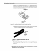
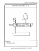
DRD203RW
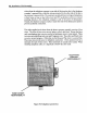
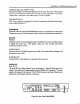
Figure 84 is the rear panel of the DRD203RW receiver. Its connection can be divided
in inputs and outputs. The following is a functional list of the jack panel connections:
INPUTS
PHONE
This jack connects the to the telephone cable. The DSS receiver uses a toll free number
to update the access card. This update usually last a few seconds and ensures
continuous program service.
SATELLITE IN
This is the 950 to 1450 MHz input from the LNB. Also carries the DC voltages from
the receiver to the LNB.
IN FROM ANT
Connect either a cable signal or an antenna to this connector.
OUTPUTS
OUT TO TV
The is the RF out (either channel 3 or 4) of the receiver. This RF can be one of two
signals. One signal, is RF signal applied to the IN FROM ANT connector. The other
signal is the output of the receiver. The TV/DSS button on the front of the receiver
determines which signal is present on the jack.
r @ooooooooo oooo ooooooo00000000001- , ,. ooooo/
I I
INFROM ,_1" _JACK
®®®
Figure 84, Rear Panel DRD203RW