
Installation guide

Installation/DishAssembly 81
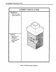
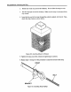
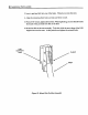
Installing the LNB Cable
Depending on the installation site and the type of system installed, there may be up to
three cables run into the home during the installation. If you are installing the basic
system, there may be up to two cables. One cable is from the dish and carries the LNB
signal to the receiver. The second cable is a telephone cable. If you are installing the
deluxe system, two cables carry LNB signals to two different receivers while the third
cable is a telephone cable. The following explanation describes the installation of a
basic system. The installation of an advanced system is the same except for the
addition of one LNB cable. A description of the telephone cable installation appears
later in this manual.
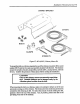
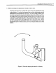
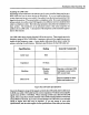
The LNB cable carries signals from the LNB to the receiver. These signals are in the
frequency range of 950 to 1450 MHz. It requires a cable with low signal loss to carry
signals in this frequency range. A poor quality cable may allow noise to enter the
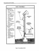
system, reducing its performance. Minimum specifications for the LNB cable are:
, Specification
Cable Type
Impedance
Shielding
Outer Cover
Rating
RG6
75 Ohms
Minimum
Double
Shield
PVC
General Comments
Requires a minimum 100%
foil shield covered with a
40% woven braid.
Must be suitable for both
indoor and outdoor use.
Figure 66, LNB Cable Specifications
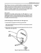
Due to the frequency range of the signals carded by the LNB cable, this be cable must
be RG6 coax cable. RG6 cable has the correct impedance (75 ohms) and acceptable
signal losses at 950 to 1450 MHz. When selecting an RG6 coax cable for the LNB
signal, select a type that is double shielded with a 100% braid foil shield covered with
at least 40% woven braid. If you are in an area that has a lot of RF noise, a woven braid
shield of higher than 40% may be required. If you are unsure of your cable
specifications, ask the cable supplier for the specifications of the cable you are using.