I DSS Sqsrem Installation Training Flanual
Foreword This publication is intended to assist the installation technician installing the RCA brand DSS TM Digital Satellite System. In this publication, basic installation techniques are covered for most common situations. Included in each explanation is a suggested material and tool list. Also included is an overview of the DSS System plus a signal flow description of the DSS receiver. This information is included to help the technician install the system and explain its operation to their customers.
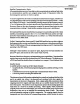
Table of Contents Overview ................................................................................................................................... 5 Technical Overview ................................................................................................................. Satellites ............................................................................................................................... Dish .......................................................................
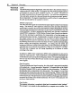
Overview Satellite Communication Basics All comm_'cations services, from ship-to-shore communications, radio and television to communications satellites are assigned unique bands of frequencies within the electromagnetic spectrum in which to operate. To receive signals from the earth successfully and relay them back again, satellites use very high frequency radio waves operating in the microwave frequency bands--either the C-band or KU-hand.
6 Overview waves into a beam of energy that is directed toward the earth. A satellite dish on the ground collects the microwave energy containing the original picture and sound information, and focuses that energy into a low noise block converter or LNB. The LNB amplifies and converts the microwave signals to yet another lower group of frequencies that can be sent via conventional coaxial cable to a satellite receiverdecoder inside the user's house.
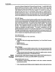
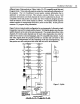
Overview _ TELUTE #1 UPLINK 5ffE PHONEUNK_IA IRD MOO_I DDDDD TELEPHONE UNE PROGRAMPRO_IOER Figure 1, Digital Satellite @stem 7
8 Overview Connections include: Satellite in: Provides direct connection from the satellite antenna/LNB. In from Ant: Provides connection from an off-air antenna or cable feed. Out to TV: Provides connection to antenna input of television. S-VIDEO: Provides direct Y/C output to compatible televisions and VCRs. Video, R/L Audio: Provides direct video and audio signals to television receivers, VCRs and audio components. Wideband Data Port: Enables reception of future services such as HDTV.
Overview Additional Menus provide: Dish positioning and adjustment. Diagnostics. Access to help screens. Ability to set-up and customize operation. Review/cancel purchases and services. # 217095 (CRK91A1) Infrared Remote Control • 30-button keypad. • Ergonomicdesign. • Provides complete satellite receiver operation. • Large color-coded buttons are clearly identified for easy operation.
10 Technical Technical Overview Overview Uplink The DSS System transports digital data, video and audio to the customer's home via a high powered KU-band satellite. The program provider sends its program material to the uplink site where the signal is digitally encoded. The "uplink" is the portion of the signal transmitted from the earth to the satellite. The uplink site compresses the video and audio, encrypts the video and formats the information into data "packets" that are transmitted.
Technical different types of data packets are Video, Audio, CA, PC compatible serial data and Program Guide. Video and audio packets contain the visual and audio information of the program. The CA (Conditional Access) packet contains information that is addressed to individual receivers. This includes customer E-Mall, Access Card activation information and which channels the receiver is authorized to decode.
12 Technical Overview Each data packet is 147 bytes long. The first two bytes (a byte is made up of 8 bits) of information contain the SCID and Flags. The SCID (Service Channel ID) is a unique 12bit number from 0 to 4095 that uniquely identifies the packet's data channel. The Flags are made up of 4 bits used primarily to control whether or not the packet is encrypted and which key to use. The third byte of information is made up ofa 4 bit Packet Type indicator and a 4 bit Continuity Counter.
Technical LONGITUDE 101 ° I UPHNK SITE DDDDD OOOOO TELEPHONEMNE, PROGRAMPRO_DER Figure 5, Digital Satellite System Overview 13
14 Technical Overview Although there are only 16 transponders per satellite, the channel capabilities are far greater. Using datacompression and multiplexing, the two satellites working together have the possibility of carrying over 150 conventional (non-HDTV) audio and video channels via 32 transponders. Dish The"dish" is an 18 inch, slightly oval shaped KU-band antenna. The slight oval shape is due to the 22.5 ° offset feed of the LNB (Low Noise Block converter), figure 6.
Technical Overview LNB The LNB converts the 12.2 GHz to 12.7 GHz downlink signal fi'om the satellites to the 950 MHz to 1450 MI-Iz signal required by the receiver tuner. Two types of LNB's are available - dual and single output. The single output LNB has only one RF connector while the dual output LNB has two, figure 7. The dual output LNB can be used to feed a second receiver or other form of distribution system. TheBasic package comes with the single output LNB.
16 Technical Overview Receiver Circuitw The receiver is a complex digital signal processor. The amount and speed of data the receiver processes rivals even the faster personal computers on the market today. The information received from the satellite is a digital signal that is decoded and digitally processed. There are no analog signals to be found except for those exiting the NTSC video encoder and the audio DAC (Digital to Analog Converter).
Technical Overview The Access Card receives the encrypted keys for decoding a scrambled channel from the transport IC. The Access Card deerypts the keys and stores them in a register in the transport IC. The transport IC uses the keys to decode the data. The Access Card also handles the tracking and billing for these services Video data is processed by the MPEG video decoder. This IC decodes the compressed video data and sends it to the NTSC encoder.
18 Technical Overview The response for all tests will be an "OK" display or an appropriate informing the customer the general area of the problem. To enter the System Test feature: Select "Options" from the "DSS Main Menu. '" DSS Main Menu Fmedrl k e_l_er mP_em h m 1Pe_eu_ 2Aeltadlor_l I 4opqn ! S_mlwfehJdlo et_'W OE5_ I 4 P_w_h_dutMp yo_ Figure 9, Main Menu Select "Setup" from the "Options" menu.
Technical Select "'System Test" from the "Setup "' menu. 1_ Dil_ P01flllng 3 IndJl A_em C_d 4 PiO_e S_e 0Bdt I Deim1"_dJyo_D_D_il_mm_l_. J Figure 11, Setup Menu Select "'Test" from the "System Test'" menu. _om Tost T_ _ _ _ t]mmM m _ a_JGT. m N lk_ MWsJ. N_IN Figure 12, System Test Menu The system test results are displayed automatically wben the test is complete. The following two screens show whether the receiver passed or failed the test.
Technical Overview ServicerControlledDiagnostics The servicer controlled test provides a more in-depth analysis of the receiver for proper operation. The test pattern checks all possible connections between components as a troubleshooting aid. The following information is provided to the servicer: 1. 2. 3. 4. 5. 6. 7. 8. 9. 10.
Technical A IOFF MESSAGE Figure 15, Front Panel Buttons Also included in the Service Test Menu are previsions for testing the modem and setting a single digit prefix number. During the service test, the modem will dial the phone number that appears in the boxes at the top of the test menu. The phone number earl be changed by using the "DOWN" arrow keys on the remote control or receiver to move the cursor past the "Prefix" prompt to the number boxes.
22 Site Survey SITE SURVEY The purpose of the site survey This planning includes is to plan the installation the locations helps to determine the tool and hardware identifies any potential problems. While performing of the Digital of the dish, receiver, Satellite and routing requirements the site survey, one of the most important System. of cables. for the installation; This plus, things to do is involve the customer.
Site Survey 37 g MINNEAPOLIS MN DISH ELEVATION 48 _ HOUSTON TX Figure 16, DSS Satellite Elevation Determine a location for the Dish. The first step in selecting a mounting site for the dish is to approximate the location of the DSS satellites in the sky. Then, select mounting site options that have the best possible view. Finally, select the best mounting location from the possible sites.
24 Site Survey MAGNETIC NORTH AZIMUTH TO DSS SATELLITES INDIANAPOLIS SEATTLE SYRACUSE 125 ° SEATTLE WA 202 ° 131 o 226 g 101 _ 80 g SYRACUSE NY I / / / 0o / 86 g INDIANAPOLIS IN 101Q Figure 17, DSS Satellite Azimuth or west of 101 ° west longitude. For example, Seattle is about 125 ° west longitude; therefore, a DSS dish must point east (about 131°from magnetic north) to point at the satellites.
Site Survey compass, first align the arrow of the compass with magnetic north. With the compass aligned correctly, draw an imaginary line from the center of the compass to the azimuth of the satellites. This is the general direction the dish must point. If possible, pick a landmark in the distance that aligns with this bearing. If not, repeat this procedure whenever confirming possible locations for the dish. To determine the elevation to the satellites, use some type of angle finder.
26 Site Survey front of the straight edge to the correct elevation. straight edge to the satellites (see figure 19). Sight along the upper edge of the With the azimuth and elevation to the satellites known, select possible mounting sites for the dish. When selecting these sites, the first and foremost thing is to ensure that there is a clear and unobstructed view of the satellites. Before installing the dish at a selected site, check the line-of-sight path to the satellites.
SiteSurvey 27 Selecting a Mounting System for the Dish There are several different mounting systems for the DSS dish. These include horizontal, vertical, and special. Use a horizontal mounting system for horizontal surfaces and vertical for vertical surfaces. Special mounting systems include pole and chimney mounts. When selecting a mounting system for the dish, consider these items: • • • Safety. Line-of-sight path to the satellite. Mounting structure.
28 Site Survey possibilities, explain them to the customer pointing out the advantages and disadvantages of each. If the customer is unsure of how they would like to connect the receiver, use your experience to recommend a hookup that will work best for them. Evaluate Off-Air Solution Local programming is not available via the DSS satellites. If the customer does not have an off-air (terrestrial) antenna or cable in the home, you may suggest the installation of one.
Site Survey • Providing up to 20 minutes of customer education on system operation. • Estimated time to complete • The "basic" install includes travel up to 25 miles (or 25 minutes in dense metro areas) for the installation without additional mileage charge to the consumer. Any installation no additional falling cost is passed that fall outside cover within a "basic" installation these on to the customer. of these guidelines, the additional guidelines expense.
30 Si_Survey Optional accessories are items that may be required for an installation but not included in the basic installation guidelines. Therefore, cost of these items can be passed on to the customer. Some example of optional accessories are: • 12' AN cables. There may be several types of cables required: stereo audio cables, video, and S-video. • Telephone accessories. These accessories include a telephone and/or modular telephone connectors (in-line and T). • Antenna system parts.
Site Survey NOTES 31
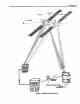
32 Installation INSTALLATION The two major components of the Digital Satellite System are the dish and receiver. These components are packed separately in the carton. The dish packaging contains five pieces. These are the dish, LNB support arm, foot and mast assembly, LNB, and a package that contains the nuts and bolts required to assemble the dish. The receiver packaging contains the receiver, remote control, RF cable, and a telephone cable.
Installation \ DISH LNB HARDWARE PACKAGE MAST AND FOOT ASSEMBLY Figure 20, Dish Packaging LNB SUPPORT ARM 33
34 Installation Before starting the installation, there some important things to remember about installing the system. First, never mount the dish on a surface that is not structurally sound. Excessive movement of the mounting surface will reduce the performance of the system. Second, whenever drilling holes in a home, follow the old rule of measure twice and drill once. Drilling a hole in the wrong place can be difficult and costly to repair.
Installation / Figure 22, Horizontal Leveling I with Bubble Level There are two leveling procedures, one for mounting the foot on a vertical surface and the other for a horizontal surface. Leveling procedures for special mounting systems are provided in the specific mounting instructions given later in this manual. The following leveling procedures gives a basic understanding of how to level the mast for each mounting system.
36 Installation When horizontal leveling with a plumb line, use the following procedure: 1. Hold the string of the plumb line over the top of the mast so it hangs as shown in figure 23. 2. Move the lower part of the foot until the plumb line aligns parallel to the side of the mast. 3. With a pencil, draw a line from center line of the mounting foot onto the wall. This line is a reference mark that enables the foot to be restored to level without using the plumb line again.
lns_l_tion ADJUST t Figure To level the mast vertically 24, Vertical Plumbing with Bubble with a bubble level, use the following Level procedure. 1. Loosen the two bolts holding the mast in position on the foot. 2. Place the level on the mast as shown in figure 24. 3. Move the mast vertically center the bubble in the window of the level. 4. Tighten the two mounting bolts securing the mast to the mounting foot.
38 Installation To level the mast vertically with a plumb line, use the following procedure: 1. Loosen the two bolts holding the mast in position on the foot.. 2. Hold the string of the plumb line over the top of the mast so it hangs as shown in figure 25. 3. Move the mast vertically 4. Tighten the two mounting bolts securing the mast to the mounting until the plumb line hangs parallel Horizontal Mounting System When mounting the foot on a horizontal with the mast. foot.
Insml_tion The important mounting thing surface. foot on a horizontal to it. For adjustment in horizontal mast leveling This is due to the one adjustment surface, example, of the foot. orient the adj u stment in the direction if you are mounting is parallel is positioning the foot on a roof, to the pitch of the roof (see figure Figure 27, Orient the Mounting Use the following of the foot When on the positioning the that h as the most angle orient the foot so the 27).
40 Installation MOVE ADJUSTMENT Figure 28, Horizontal Surface Mast Leveling with Foot Adjustment SPACERS (IF REQUIRED) Figure 29, Horizontal Surface Side to Side Leveling
Installation . , Move the bubble level (or plumb line) 90 degrees and measure. If level, double check both measurements and secure the foot (skip steps 5 and 6). If it is not level, continue to step 5. If the side to side measurement of the mast is not level, use spacers to level it. To use spacers, determine the side that must be raised. Then, place 5/16 washers under the foot to level the mast. Position these washers under the mounting 6, holes so the mounting bolts will secure them.
42 Installation/Mounting the Dish PANEL SIDING Material List: • 2EA. I/4 "x3" screws. 5 Lag II • 4EA /16 xlV2"Lag screws. • 2EA. 1/4 Flat washers. • 4 EA. 5/is" Flat washers STUD __ WOOD PANEL I Tool List: • Drill. • l/s" Twist drill bit. 3/16"Twist drill bit. • Bubble level or plumb line. • • 7/16"Box or open end wrench. 3/s" Box or open end wrench. • Pencil.
Installation/Mounting Panel siding is typically a 4' x 8' sheet of material mounted over some type of insulating sub layer. The thickness of these panels varies from 3/8" to 5/8". Nails secure the panels to the frame structure of the home. Usually, the edges of panels are cut so that lap joints form where two panels meet. This provides a relatively flat mounting surface for the DSS dish. Panel siding can be made of many different types of materials.
44 Installation/Mounting the Dish 2. Place the mounting foot on the panel aligning the center holes with the center of the stud. With a pencil, mark the upper center hole of the mounting foot. 3. Remove the mounting foot and drill a 1/8" hole in the location just marked. J With a 114" x 3" lag screw and washer, attach the mounting foot to the wall using the hole drilled in step three. Tighten the lag bolt until it just holds the mounting foot to the wall.
Installation/Mounting LOOSEN Figure 32, Loosening required for the installation. of the dish. 12. Vertically Lower Nuts These screws reduce the side-to-side movement level the dish with a bubble level or plumb line. To do this, place the level, or plumb line, on the mast at an parallel angle to the wall. If you have not loosened the two bolts securing the azimuth adjustment on the mounting foot, do it now.
46 Installation/Mounting the Dish LAP SIDING Material • List: 2 EA.I/4" x 3" Lag • 4 EA. s/16" x IV2" Lag screws. • 4 EA. 5/16"Flat washers. • _>.2x4 STUD / SCI_WS. 2 EA. 1/4" Flat washers. I r Tool List: • Drill. • • • ]/s" Twist drill bit. /16 Twist dnll bit. Bubble level or 3 it . . . (Optional) plumb line. • • • 7 Ig 1,6 Box or open end wrench. 3 CENTER HOLE STUD \I " /8 Box or open end wrench. I-I Pencil. /I OUTSIDE \ HOLES _ I "° Figure 33, Mounting I\ I I/ OUTSID
Installation/Mounting theDish 47 Lap sided walls are made up of many narrow boards stacked horizontally up the wall. Each board is lapped by the board above it. Usually, all the boards on one wall are the same width; however, the width of lap siding material can vary from 4 to 10 inches. Therefore, it is possible for one wall to use 5" boards and another wall to use 7" boards. This can make finding alocation on the wall wide enough for the mounting foot difficult.
48 Installation/Mounting \ the Dish FACE WIDTH w m -- B \ Figure 35, Lap Siding Face Width Another difference with the siding styles that do not have flat surfaces is the different amount of exposed board, called the face width. For example, the face width of bevel and taper siding styles can vary from 3-1/2" to 9". This presents a problem when mounting the DSS foot to boards with the narrower face widths. The mounting foot is about 7" long and mounts across a board.
Installation/Mounting Lap siding can be made from many different types of materials. These materials range from solid wood to aluminum. Do not mount the DSS Dish on any type of aluminum or vinyl siding,. We also do not recommend mounting the system on any type of composite material. This includes strand board, chip board, fiber board, and particleboard. An acceptable siding material is solid wood or plywood. There are also several types of solid wood siding sold today.
50 Installation/Mounting the Dish 5. Horizontally level the mast using either a bubble level or a plumb line. To horizontally level the mast, place the level, or plumb line, on the mast at an perpendicular angle to the wall. If you are using a bubble level, move the bottom of the mounting foot to center the bubble in the window of the level. If you are using a plumb line, move the lower part of the foot until the plumb line hangs parallel to the side of the mast.
Installation/Mounting 13. Check the tightness of all bolts and proceed to the Assembling the Dish section. Installing a Spacer (Optional) If the siding is too narrow for the mounting foot, a spacer must be installed. The spacer can be held in place by the lower two mounting bolts of the mounting foot. To do this, use the following steps. 1. Remove the lag bolts from the lower outside holes of the mounting foot. 2.
52 Installation l Mounting the Dish BRICK WALL Material List: • 4EA. l/4" Wall anchors. • 4 EA. 1/4" x 11/2" Machine screws. • 4EA. V4"Flat washers. Tool List: • Drill. • • • • • • V2"Masonry drill bit. Bubble level or plumb line. 7116"BOX or open end wrench. 3/." Box or open end wrench. Hammer. Pencil. a, ? OUTSIDE OUTSIDE/ HOLES _ HOLES \(o Figure 38, Mounting Foot and Mast Assembly to a Brick Wall
Installation/Mounting the Dish 53 Using wall anchors, the foot can be mounted to most brick walls. Wall anchors insert into a hole drilled into the brick. These anchors come in a variety of types and sizes. When selecting 300 pounds 114" Rawl a wall anchor to use, select one that will work in brick and has at least of pull out strength. brand double expansion An example anchor of a wall anchor for the DSS dish is a (BB4015).
54 Installation/Mounting the Dish 1 3/4" DEPTH (MINIMUM) BRICK J Figure 37, Drilling Holes for Wall Anchors 7. Horizontally level the mast with a bubble level or plumb line. To horizontally level the mast, place the level, or plumb line, on the mast at an perpendicular angle to the wall. If you are using a bubble level, move the bottom of the mounting foot to center the bubble in the window of the level.
Installation/Mounting 11. Insert expansion anchors in each hole. 12. Use four 1/4" x 20 x 1-1/2" machine mounting 13. Vertically screws and 1/4" washers to attach the foot to the wall. Tighten all four screws. Level the dish with a bubble level or plumb line. To do this, place the level, or plumb line, on the mast at an parallel angle to the wall. If you have not loosened the two bolts securing the azimuth adjustment on the mounting foot, do it now.
56 Installation/Mounting the Dish CINDER BLOCK WALL Material List: • 4EA. V4"x3" Machine screws. • 4 EA. 1/4"Hollow wall anchors or • togglers. 4 EA. 1/4" Flat washers. Tool List: • Drill. • 1/2" Masonary drill bit. Bubble level or • plumb line. • • • 7/16"Box or open end Screw driver. Pencil.
Installation/Mounting Cinder blocks can come in a variety of sizes. These sizes vary in length and in the number of cores, or cavities, in the block. The block sizes are three core (8" x 8" x 16"), two core (8" x 8" x 16"), and a smaller two core (8" x 8" x 12"). In many areas, the two core 16" block is the most common.
58 Installation/Mounting the Dish Installing the Mounting Foot on a Cinder Block Wall Using Togglers: When following these instructions, take extreme care to avoid contact with overhead power lines, lights, and power circuits. DANGER! Contact with power lines, lights, and circuits may prove fatal. J 1. Select a mounting location. Remember to position the foot so the outside holes align with the hollow cores of the cinder block. 2. Hold the mounting foot in position holes. 3. Remove 4.
Installation/Mounting WALL PLASTIC CAP CHANNEL RING Figure 43, Toggler Installation Step 2 4.3. Place thumb between plastic straps. Push side to side snapping off straps flush with wall. Figure 44, Toggler Installation Step 3 5. With the 1/4" x 20" x 1-1/2" machine screw and 1/4" washer, attach the mounting foot to the wall. This screw should be tightened until the mounting foot is snug against the wall (Do not overtighten).
60 Installation/Mounting the Dish VERTICAL LEVELING HORIZONTAL LEVELING Figure 46, Horizontal and Vertical Leveling
Installation/Mounting theDish 61 6. Horizontally level the mast with a bubble level or plumb line. To level the mast horizontally with either a bubble or plumb line, place them on the mast at an perpendicular angle to the wall. If you are using a bubble level, move the bottom of the mounting foot to center the bubble in the window of the level. If you are using a plumb line, move the bottom of the mounting foot until the line hangs parallel with the mast.
62 Installation/Mounting the Dish DECK RAILING Material List: 5 Ii • 4 EA. /16 x 1112" Wood lag screws. • 4 EA. 5/16" Flat washers. Tool List: Drill. • sit6" Twist drill bit. • Bubble level or plumb line. • Screwdriver. • Pencil.
Installation/Mounting When selecting horizontal mounting surface for the DSS dish, select one that is both structurally sound and offers some protection from traffic. Do not position the dish where it may be used as a hand rail or have objects hung from it. Deck railings and floors are examples of good mounting surfaces for the system if the right location is chosen. The type location of mounting material the system of the bolts used to secure a 2 x 4 or 2 x 6 board, are mounting holes.
64 Installation/Mounting the Dish ROOF INSTALLATION Material List: • 2 EA. 1/4" x 3" lag screws. • 4EAS16"x 11/2'' lag screws. • 2 EA. 1/4"Flat washers. • 4 EA. 516"Flat washers. • Roof Sealant. Tool List: • Drill. CENTER HOLE • V8"Twist drill bit. • 3/16"Twist drill bit. • Bubble level or _._ii i_ j- RAFTER plumb line. • 7/16" Box or open end wrench. • 3/8" Box or open end wrench. • Ladder. • Pencil. OUTSIDE / HOLES I _ I NOUTS I/ i i\ , , HOLEs CENTER HOLE Figure 48, Mounting F
Installation/Mounting the Dish 65 Do a roof installation only if there is no other mounting option for that installation site. This is due to the difficulties of installing a satellite dish on a roof. These difficulties include damaging the roof by walking on it or causing leaks by not correctly sealing the mounting holes. These problems increase with the age of the roof and the type of roofing materials. If you do install the dish on a roof, do it only on asphalt type shingles.
66 Installation /Mounting theDish RAFTERS TRANSFER MEASUREMENT TO ROOF SHINGLE OVERHANG FACING BOARD MEASURE FROM ROOF EDGE TO NAILS Figure 50, Locating Rafters To locate the rafter near the mounting site, look at the facing board near the site. Locate the closest nails securing the facing board. Measure from the edge of the roof to the nails and record that distance. To find a rafter near the mounting location, transfer the previous measurement to the roof.
Installation/Mounting 2. Position the mounting rafter. foot so that the center two holes align with the center of the 3. Mark the two center holes (the mast may need to be repositioned the second hole). 4. Drill two 1/8" holes in the locations marked. Fill each hole with a small amount of roof sealant. 5. Attach the mounting washers. for marking of foot to the roof with two 1/4" x 3" wood type screws and 6.
68 Installation/Mounting the Dish POLE MOUNT Material • List: • • 1 EA. 1 1/4" ID Schedule 40 galvanized steel pipe (11/20D). 3 Bags quick setting concrete. 1 EA. 1 l/2" Ground clamp. 1 EA. Ground rod 1 EA. Ground rod • clamp. Ground Conductor • (NO. 10 copper or NO. 8 aluminum). Wire ties. • • 1 1/4 I.D. ]k SCH40 Tool List: • • • • Hole digging tools. Hammer. Wheelbarrow. Bubble level or • plumb line. Assorted box or • • open end wrenches. Screwdriver. Pencil.
Installation/Mounting In this mounting system, a pole replaces the foot and mast assembly supplied with the DSS dish. This pole is placed in a hole and secured in the ground with concrete. The dish is held on the pole by the clamp of the LNB support arm. This clamp fits over the pole. Before installing the dish on a pole, carefully read the following: • Have the local utilities locate the power, telephone, lines in the area before you do any digging.
70 Installation/Mounting the Dish 1. Dig a 8" diameter hole at least 26" deep. CAUTION: Before you dig, call your local utility and phone company for help In locating underground utility lines. o With a hack saw, cut bottom edge of the pole to about a 45 °. This prevents from rotating in the concrete over time. the pole POLE t CUT Figure 53, Cutting Bottom of Pole at an Angle 3. Place the pole in the hole and fill the hole with just enough dirt, or small stones, to hold it upright. 4.
Installation/Mounting GROUNDING CONDUCTOR CLAMP ROD GROUND ° o Figure 55, Grounding Pole least two different locations on the side of the pole. should be at right angles to each other. These two measurement Note: The dirt or stone placed in the hole in step two should hold the pole upright. If not, attach guy wires to the pole to keep it upright. 5. With prepared quick drying cement, fill the hole. Stop filling when the cement level is about two inches from the top of the hole.
72 Installation/Mounting the Dish CHIMNEY INSTALLATION Material List: • 1 EA. RCAD915 chimney mount kit. Tool List: • Bubble level or plumb line. • 7/1_" Box or open end wrench. • Ladder.
Installation/Mounting CHIMNEY BRACKET ! STRAPS CLAMPS EYEBOLTS Figure 57, RCA (D915) Chimney Mount Kit To mount the dish on a chimney requiresthe use of the chimney mount kit (RCA model number D915) and the foot and mast assembly included with the dish. The chimney mount kit includes a bracket, straps (2EA), eye bolts (2EA.), clamps (2 EA), and bolts (4 EA.). Confirm the presence of these pieces before starting the installation. CAUTIONI Only use the chimney mount on structurally sound chimneys.
74 Installation/Mounting the Dish Before climbing a ladder, following steps: assemble the chimney mount kit. To do this, use the 1. From the chimney mount kit, locate the straps and chimney bracket. Each metal strap in the chimney mount kit has a pre-attached eyebolts. Insert both strap's eyebolts in the appropriate hole in the chimney bracket. 2. Thread a nut on the eyebolts and tighten it to about 1/2" from the end ofthe eyebolt. 3. Repeat steps 1 and 2 for the second metal strap. 4.
Installation/Mounting ! FOOT BOLTS Figure 59, Assembly of Chimney Mount Kit Steps 6 and 7 7. Secure the mounting foot to the chimney bracket with the four bolts supplied with the chimney mount kit. With the chimney mount assembled, following steps to do this: 1. install the mount on the chimney. Place the chimney bracket on the comer of the chimney Use the as shown. Danger! When following these instructions, take extreme care to avoid contact with overhead power lines, lights, and power circuits.
76 Installation/Mounting the Dish 2. Stretch one metal strap around the chimney. 3. Pull the strap tight around the chimney. way around. 4. Insert the free end of the strap through the eyebolt supplied attach the strap clamps as shown below. Figure 60, Attaching Do not allow the strap to twist. Make sure the strap is horizontal all the with the kit. Then, Mount to Chimney 5. Tighten the strap around the chimney by tightening 6. Repeat steps 1 through 5 of this procedure its eyebolts.
Installation/Mounting 7. With the mounting foot adjustment, vertically level the mast. To do this, place the level, or plumb line, on the mast at an perpendicular angle to the chimney. If you have not loosened the two bolts securing the azimuth adjustment on the mounting foot, do it now. If you are using a bubble level, move the mast vertically to center the bubble in the window of the level.
78 Installation/Dish Assembly DISH ASSEMBLY Material List: • RG6 coax cable. • Coax cable ground block. • "F" fittings for RG6 coax cable. • Ground Conductor (No. 10 copper or No. 8 aluminum wire). • Telephone wire (minimum two conductor). • RJll/14 telephone plugs. • Coax cable sealant. • Silicon sealant. • INSTALL LNB l .if _" ASSEMBLE DISH INSTALL LNB CABLE CONNECT Cable clips. Tool List: • Drill. • • • 1/2" Twist drill bit. Adjustable wrench. Phillips head screwdriver. • Hammer.
Installation/Dish Assembly This section uses four steps to assemble the different components of the DSS dish antenna. The first and second steps are assemble the dish and install the LNB cable. The third step explains the installation of the LNB. This includes connecting the LNB cable to the LNB and fastening the LNB to the dish. Finally, the fourth step points out the basics of installing a telephone cable.
80 InstallationZ Dish Assembly 3. insert a pan head bolt into one of the holes. 4. Align the remaining Thread a nut onto this bolt. three holes and nuts and bolts in each. 5. With a 7/16" wrench, tighten all four bolts. When tightening, the heads of the pan head bolts flat on the dish. use your thumb to hold 6. Mount the dish on the mast assembly. To do this, slide the mast clamp of the LNB support ann over the mast. At this point do not tighten the azimuth bolts.
Installation /DishAssembly 81 Installing the LNB Cable Depending on the installation site and the type of system installed, there may be up to three cables run into the home during the installation. If you are installing the basic system, there may be up to two cables. One cable is from the dish and carries the LNB signal to the receiver. The second cable is a telephone cable.
82 Installation / Dish Assembly Depending on the routing of the LNB cable, you may want to use a type that can be buried. When normal coax cable is buried, soil decays its outer cover and shortens its life. Cables that are suitable to be buried use a special outer cover that resists breakdown. Some of these cables also place a special coating on the ground shield. This coating resists corrosion caused by water which could get in the cable. Anytime the LNB cable is buried, use cable that can be buried.
Installation GROUND BLOCK DRIP LOOP COAX CABLE GROUND CONDUCTOR GROUND WIRE CONNECTION Figure 68, Coax Cable Ground Block and Drip Loops The LNB cable supplies the signal from the LNB to the receiver. This cable also carries the DC power to the LNB from the receiver. For the LNB to receive power and operate, it is important that any splitters or amplifiers inserted in the LNB cable must pass DC. Another important aspect of the LNB cable installation is grounding.
84 Installation/DishAssembly between the ground block and ground electrode) must be in a straight line, if possible, from the ground block to the grounding electrode. Also, splices in the conductor between the electrode and grounding block are prohibited. Article 820-33 of the National Electrical codes also states that, "Where coaxial cable is exposed to lightning •.. the cable ground shall be connected to the grounding system of the building, as close to the point of cable entry as practical.
Installation 3. Connect 4. Route the cable from the ground block to the dish mounting foot. Leave enough slack in the cable to form a 3" to 5" drip loop. Also, leave enough cable to reach the LNB from the mounting foot (about 3 feet). 5. Secure the cable with cable clips. it with cable clips. 6. Install the ground conductor 7. Route the ground conductor to the grounding electrode. cable to a wall or some surface to protect it. 8.
86 Installation / Dish Assembly Attaching the LNB The LNB attaches to the LNB support arm. To do this step, you will need the LNB mounting bolt, washer, and nut from the hardware packet. You will also need to remove the LNB from the packaging. The tools you will need are a Phillips head screwdriver and the tools required to install an F-type connector (you will only need this if the cable is not pre-terminated with an F-fitting).
Installation LNB CONNECTOR LNB CABLE Figure 71, Connecting LNB Cable To LNB 2. Install an F-type connector on the end of the cable. connector on it, disregard this step. If the cable already has a 3. Thread the coax cable onto the LNB connector. 4. If the connector is not weatherproof, seal it. 5. Slide the end of the LNB into the rectangular opening of the LNB support ann. Position the LNB to align it with the hole in the support arm. 6.
88 Installation / Dish Assembly Attaching the LNB Cable to the Receiver In the next step of the installation, route the LNB cable from the ground block to the receiver. In most installations, there is more than one way to get the LNB cable to the receiver from the grounding block. If the receiver is located on an outside wall, go through the wall. If the receiver is on an inside wall, use crawl, basement, or attic spaces.
Installation CONNECT LNB CABLE u: .e. 0000000000000 O00000000O! 0000000 E_::=o) Figure 74, Connect LNB Cable to Receiver's "Satellite In" Jack 4. With cable clips, secure the drip loop and cable to the wall. 5. In the home, route the cable to the rear of the receiver. Depending on the installation site, this could be through a floor or directly to the rear of the receiver. If the cable goes straight though a wall, a wall plate may be used to dress up the access point.
90 Installation / Dish Assembly GROUNDING CONDUCTOR MOUNTING HOLES Figure 75, Attaching Grounding Conductor to Mounting Foot The National Electrical code is also very specific on acceptable electrodes ground. Some possible grounding electrodes are: for the Grounded Interior Metal Water Pipe (cold water). Ground Rod (must be driven at least 8 feet into the ground). Grounded Metallic Service Raceway. Grounded Electrical Service Equipment Enclosure.
InstaUation 2. Route the grounding conductor to the grounding electrode. use the shortest and straightest possible path. While doing this, 3. Attach the grounding conductor to the grounding electrode. The method of attaching the conductor will vary with different grounding electrodes, use the correct method for the electrode you are connecting to. 4. Secure the grounding conductor to a wall or other surface. be protected from physical damage.
92 Installation / Dish Assembly wiring from the telephone company to one side of this junction box is the telephone company's responsibility, while the wiring connected to the other side of the box is the customer's responsibility. The customer can add additional wiring and telephones to their home as long as they follow local and FCC guidelines and do not connect anything directly to the telephone company's side of the point of demarcation.
Installation/ DishAssembly93 COLORS VARIATION 1 VARIATION 2 VARIATION 3 RED BLUE WITH A WHITE STRIPE BLUE WITH A WHITE STRIPE BLUE GREEN WHITE WITH A BLUE STRIPE WHITE WITH A BLUE STRIPE WHITE YELLOW ORANGE WITH A WHITE STRIPE ORANGE WITH A WHITE STRIPE ORANGE BLACK WHITE WITH AN ORANGE STRIPE WHITE WITH AN ORANGE STRIPE WHITE WITH AN ORANGE STRIPE N/A GREEN WITH AN WHITE STRIPE N/A WHITE WITH AN GREEN STRIPE Figure 77, Telephone Wire Color Code There are cables that use a slight va
94 lnstallation / Dish Assembly Use the following procedure to install a telephone jack: Never work with active telephone lines. When the telephone is ringing, the current carried on these lines may shock you. While working on the telephone line, disconnect the wiring at the point of demarcation. If SAFETY NOTE: to do this, take all the telephone you are unable handsets off the hook. I. Find an accessible telephone junction box (this could even be the point of demarcation).
Installation/Dish Assembly95 Modular Plug Installation Different modular crimping tools have slightly different procedures. the procedure the accompanies the crimping tool you are using. 1. With the cable cut to length, trim the ends so they are straight diagonal. Follow and not 2. Strip approximately 3/8" from the outer conductor of the cable (this is for fiat four-conductor telephone line and may vary slightly for twist and outdoor cable).
96 Installation / Dish Assembly NOTE: hardwired In most installations, to a junction box. the other If you must other end of the cable, the orientation Oriented this cable as shown end of the telephone install a modular cable will be connector on the of the wire in the connector in figure is different. 81. Spring Clip MODULAR CABLE Figure 81, Installing a Modular Plug On a Modular Line Cord 4.
Installation/Dish Use a Wireless Phone Adaptor These units use the AC wiring of the home to connect a remote telephone or the DSS receiver to the telephone lines. Wireless phone adaptors usually include two pieces. One piece, called the base unit, plugs into an AC outlet near an existing phone jack. A modular telephone cable then connects between the existing phone jack the base unit. The second piece, called the extension jack, plugs into an AC outlet near a remote phone or the DSS receiver.
98 Installation/Installing the Receiver Installing ....e !0 01! Receiver the _[[ fZ _ _, [ J Figure 83, Rear Panel DRDIO2RW All connections to the receiver are made at the back panel. These connections are slightly different for the two models of receiver's. DRD102RW Figure 83 is the rear panel of the DRD 102RW receiver. Its connection can be divided in inputs and outputs.
Installation/Installing the Receiver AUDIO R (fight) and AUDIO L (left) This is left and right channel audio signal from the receiver. If you are connecting the receiver to a monitor type of television, connect these to the audio inputs. You can also connect there connectors to the audio input of a stereo amplifier. Wide BAND DATA This 15 pin connector is designed such as high definition TV. to be used in conjunction with future technology: DRD203RW Figure 84 is the rear panel of the DRD203RW receiver.
100 Installation/Installing the Receiver The RF channel output on this jack is controlled by the RF switch. When the switch is in the channel 3 position, the RF out will be channel 3. The same is true for channel 4. S-VIDEO This connector outputs an S-video signal to a compatible S-video connector can be inserted into this jack. television or VCR. Only an VIDEO These two connectors are bridged in the receiver. Because they are bridged, both have the same signal on them.
Installation/Installing RECEIVER (DRD102RW) TOTV SATELLITE RECEIVER TV Material I List: • 1 EA RF Cable (must have screw type of Fconnectors) Figure 85, Basic Hookup With Either DRDIO2RW or DRD203RW the Receiver 101
102 Installation/Installing the Receiver RECEIVER (DRD 102 RW) -i to VCR and TV m .i ii' N SATELLITE _',_:_O000UOOHOOD_O_O0000 0000000000_00000 L i , :. ,._o_@@ @ yi// _,o_--°_ _ [] @ @_ •_i_- Material List Basic Hookup: • 2 EA. RF cables (use only cables with screw type F connectors). • 1 EA. Video cable. • 1 EA. Stereo audio cable. Figure 86, Hookup Of Receiver I '- VCR @@@ _ If A ,., L Material List Monitor TV Hookup: • 1 EA. Video Cable. • 1 EA. Stereo audio cable.
Installation/Installing RECEIVER Material (DRD 203RW) List Basic Hookup: • 2 EA. RF cables (use only cables with screw type F connectors). • 1 EA. Video cable. • 1 Elk. Stereo audio cable. the Receiver to VCR and TV Material List Monitor TV Hookup: • 1 EA. Video Cable. • 1 EA. Stereo audio Cable.
104 Installation/Installing the Receiver Figure 86 incorporates a VCR in the connection system. This system is shown using the DRD102RW receiver. This connection system applies the RF signal from an antenna, or cable, to the RF in of the receiver. The RF output of the receiver is sent to the VCR ANT IN connector. The OUT TO TV connector of the VCR is connected to the ANT IN of the television. These RF connection enables the VCR to record either the antenna signal or the satellite signal.
Installation/Aligning This step of the installation accurately points the dish at the satellites. This alignment is critical to the performance of the system. When the dish is pointed directly at the satellites, the receiver receives a strong signal. Any drop outs in this signal would be small and corrected in the receiver. If the dish is not positioned properly, the signal is weak and the number of drop outs increases.
106 Installation/Aligning the Dish There are four steps to align the dish: 1. Determine the azimuth and elevation settings for your geographic location. 2. Adjust the elevation. 3. Adjust the azimuth. 4. Acquire and fine tune a signal. To align the Digital Satellite System, first find the approximate position of the satellites at the installation site. Then adjust the azimuth and elevation to point the dish at the satellites.
Installation/Aligning 3. To use the zip code method, select the "Pointing Dish using Zip Code" category of the menu. Once selected, the Enter Zip Code screen appears. Enter the installation site's five-digit zip code in the boxes provided and then select the OK box. The next screen that appears is the "Dish Pointing" screen. This screen gives both the azimuth and elevation. Dish F_intino 4_ _ Figure 89, Dish Pointing Coordinates 4. On a piece of paper, record the azimuth and elevation coordinates.
108 Installation/Aligning the Dish ao 40 5060 Figure 90, Elevation Adjustment 2. Move the dish to point the LNB in the direction of the satellites (this is the azimuth coordinate determined in step I). This step assumes the azimuth bolts of the LNB support arm have not been tightened. If they are tight, loosen them until the dish moves from side to side freely.
Installation/Aligning the Dish 8kDnml _t_ We=_ Slrang Figure 92, Signal Strength Menu Acquiring and fine tuning the Dish Position. In the previous steps, the azimuth and elevation were adjusted to point the dish in the general direction of the satellites. The next step of the installation uses the receiver's alignment system to fine tune the position of the dish. The receiver's signal strength screen uses two systems to help you to fine tone the position of the dish.
110 Installation/Aligning the Dish When aligning the dish, move the dish only after the receiver is finished with one complete search routine. Both the on-screen display and audio tone signal the end of a search routine. The video display will flash the "Rotate the Dish 3 Degrees" prompt every other search routine. This ensures the receiver has had the chance to complete one complete search operation before the dish is moved again. The receiver outputs a tone burst at the end of every search routine.
Installation/Aligning ALIGNMENT TAPE Figure 95, Adjusting Azimuth . TICK MARKS with Alignment Tape Continue this sequence and stop at the signal strength display's largest number or the longest bar display. If you turn the dish all the way to one direction without locking on a good signal, move back to the starting point and repeat the same process in the opposite direction. If you do not get a signal, see the troubleshooting section of this manual. 6.
112 Installation/AligningtheDish J SECOND MARK FIRST MARK CENTER MARK Figure 96,Azimuth Adjustment with Audio Tone Aligning with the Audio Tone 1. To listen to the audio tone, use a television, stereo, or wireless headphones. Connect the satellite receiver's audio output connector to the device you are using. . Gendy turn the dish either right or left one tick mark of the alignment tape and pause. If the receiver outputs a continuous tone, mark that position on the mast.
Installation/Aligning theDish 113 Note: It is possible the signal tone strength stops. starting mast. Mark point. increments. Once that a continuous menu. that position Now, rotate Stop rotating that is done, tone is received If so, move immediately the dish in three degree on the mast and return the dish in the opposite the dish when the tone stops.
114 Troubleshooting Troubleshooting To make troubleshooting easier, the DSS receiver has a diagnostic system built into it. This system makes several checks of key areas in the receiver to determine their status. The tests made are in the following areas: • • • • Signal Tuning Telephone Access Card Once the receiver completes these checks, the on-screen menus displays the results of each check. For example, if the tuner checks good, the on-screen display will indicate it is OK.
Troubleshooting 115 If the on-screen menus are visible on the television, use the receiver's diagnostics menus to help determine the problem. To do this, use the front panel controls or IR transmitter of the receiver to place it in the customer test mode. Once in the test mode, the receiver runs four tests. An explanation of these tests is in the technical overview section of this training manual.
116 Troubleshooting Step 2 Step 2 verifies the dish is pointed at the satellites. To confirm this, use the signal strength meter in the receiver's alignment menu. This menu has two indicators that are important to troubleshooting. These are signal strength and lock. The signal strength meter indicates the amount of signal received by the receiver. The lock indicator indicates whether the received signal is the DSS signal.
Troubleshooting117 Tuning The tuner check indicates whether the receiver's tuner is tuning to a satellite transponder. If the signal strength is good but the tuning test fails, suspect a defective receiver or LNB. Phone During the phone portion of the self test, the receiver checks for a dial tone and performs an internal loopback test. If the phone test detect a problem, it will put the message "Check phone connections" on the screen.
118 Appendix A / Finding DSS Azimuth and Elevations A coarse alignment of the satellite antenna to locate the satellite can be accomplished by using the following map and charts. The map shows latitude and longitude lines running through the United States. The additional curved lines on the map represent the magnetic variation of the earth's magnetic field. The charts show what azimuth and elevation to use when pointing the dish for a given location.
Appendix A / Finding DSS Azimuth and Elevations 120 \ Latitude Longitude Map of United States.
120 Appendix A/Finding DSS Azimuth and Elevations SATELLITE 101 g WEST LATITUDE .ONGITUDE *MAG, DECL. TRUE NORTH AZ *MAG. NORTH AZ ELEV. 25 60 +2 222 224 52.5 25 85 0 214 214 55.7 25 90 -4 2O5 201 58.3 25 95 -6 154 188 60.0 25 100 -8 174 60.8 25 105 -9 171 163 60.4 25 110 -10 159 149 50.1 25 116 -12 140 137 56.8 30 80 +3 218 221 48.2 30 85 0 210 210 50.9 30 90 -3 201 198 53.0 30 95 -6 186 54.4 30 100 -8 174 56.
Appendix A / Finding DSS Azimuth SATELLITE 101_ WEST LATITUDE LONGITUDE *MAG. DECL. TRUE NORTH AZ *MAG. NORTH AZ ELEV. 45 65 +20 226 246 27.2 45 7O +18 220 238 29.8 32.1 45 75 +13 215 228 45 8O +8 209 217 34.1 45 85 +3 203 206 35.8 45 9O -1 105 194 37.0 45 95 -5 188 183 37.8 45 100 -10 181 171 38.2 45 105 -13 174 161 36.9 45 110 -16 167 151 37.4 45 115 -17 161 144 36.3 45 120 -18 154 136 34.0 45 125 -18 148 130 33.
122 Appendix A / Finding DSS Azimuth 3. and Elevations Press DSS on the receiver's remote control. 4. Press MENU on the remote control to bring up the Main menu. Note: Each of the receiver's screens includes instructions that will help you use the menu system. 5. Select Options, 6. Select Setup. 7. Select Dish Pointing. 8. Select Point Dish Using Your Zip Code to bring up the Zip Code display screen. 9. Enter your zip code using the number keys on the remote control. you have finished.
AppendixA / Finding DSSAzimuthand Elevations 123 The DSS receiver can also use the latitude and longitude of the installation site to determine the azimuth and elevation to the DSS satellites. There two steps to do this. The first is to determine the latitude and longitude of the installation site. In the second step, that site's latitude and longitude are used to determine the azimuth and elevation to the DSS satellites.
124 Appendix Finding the Magnetic Azimuth B / Using a Compass The magnetic azimuth is the directional reading in degrees taken directly fi'om the compass. This reading represents the number of degrees offofmagnetic north. For example: East - 90° Azimuth West - 270 ° Azimuth South - 180° Azimuth North - 0° or 360° Azimuth of compasses are commonly used to fred the magnetic azimuth.The "standard" compasshasafixeddialwith a"needle" that alwayspointstoward magnetic north.
Appendix B / Using a To find the magnetic azimuth with the standard compass, rotate the compass so the needle lines up on the O*(north) mark. The compass is now aligned with magnetic north and the azimuth degrees are the same as the degree markings on the dial. 60* AZIMUTH 120*AZIMUTH To find the magnetic azimuth with a lensatie compass, first align the reference mark with the sight. Then look at the degree markings through the lens.
126 Appendix C/National The following is the portions Electrical Code of the 1993 National Electrical Code that pertains to the installation of the Digital Satellite Systems. These are only pieces of the complete code and if there are any questions the National Electrical Code handbook should be consulted. Also, before doing any installations in an area, it is important to check for any local codes that would pertain the installation of the system. 250-1.
Appendix C/National Electrical Code 127 250-83. Made and Other Electrodes. Where none of the electrodes specified in Section 250-81 is available, one or more of the electrodes specified in (b) through (d)* below shall be used. Where practicable, made electrodes shall be embedded below permanent moisture level. Made electrodes shall be free from nonconductive coatings, such as paint or enamel.
128 Appendix C/National Electrical Code 250-115. Connection to Electrodes. The grounding conductor shall be connected to the grounding electrode by exothermic welding, listed lugs, listed pressure connectors, listed clamps, or other listed means. Connections depending on solder shall not be used.
Appendix (e) C & D/DSS Reference Publications 129 Run in Straight Line. The grounding conductor for an antenna mast or antenna discharge unit shall be run in as straight a line a practicable from the mast or discharge unit to the grounding electrode. (f) Electrode.
130 Appendix D /DSS Installers Reference Guide Thomson Consumer Electronics IRCA Brand DSS 1 DSS Service Support Line ........................................................................................... Consumer should call this number to resolve service and use and care questions. 1-800-679-4776 DSS Installation Support Line ....................................................................................
Appendix "BASIC" INSTALLATION GUIDE D/DSS Installers Reference Guide 131 LINES • The dish unit can be mounted on a stable structure of the dwelling - a vertical wall, chimney, or roof, within a 100-foot cable length of the connected TV. Hardware necessary to mount the dish must be provided by the installer and included in "basic"installation price. This includes screws or bolts, grounding hardware, and an occasional inexpensive Thomsonapproved chimney mount.
132 Appendix E / RCA DSS Dish Parts List 22111HS 22t197 RCA STOCK NUMBER DESCRff'TION 221197 #_nt_nna, 18" S_I, RCA DSS, Dark Gray, DSAI00RW 221196 Kn_.ana, 18" S_I, DSS logo oRly, I_a'k Gray, DSA 112NW/DSA2] 2NW 221198 _nnL 221199 _,lounting Bre_k_ Assembly, Dark Gray, (S_l 2212[_ _lounting Bracket Assembly, Light Gray, ($MC An_m_), DSA400RW 221201 Base.'Tube Assembly, I:ha'kGrimy,($te_l Annum) DSA 100RW/112NW/212NW 221202 8_wTube 217333 [.
Glossary 133 GLOSSARY A Alignment The process of adjusting the satellite dish to receive the strongest satellite signal. Azimuth Left and right adjustments compass, measured to determine point B to your satellite in a clockwise the location the dish towards dish. direction of the satellite's from relative Technically, the degrees true North. position of rotation This information to your home on a can be used and help you to the satellite.
134 Glossary E Earth Ground Conducting connection to the earth for an electrical charge so that the electrical charge is at zero potential with respect to earth. Elevation Up and down adjustments of you dish. Technically, the vertical angle that is measured from the horizon up to the satellite. This information helps you locate the satellite and point the dish toward it. F F Connector A special type of connector used commonly to terminate coaxial cable. Feedhorn The input of the LNB.
Glossary M 135 Main Menu The first menu in the on-screen menu system. Menus are lists of choices that allow you to customize the DSS Receiver and access features available through the on-screen menu system. Mast Metal pipe attached to the mounting foot. Supports mounting system, the metal pole is the mast. P the LNB support arm and dish. In a pole Plumb Line String with an attached weight that provides a reference line perpendicular to the ground.
136 Index Index Symbols # 217095 Remote 16x9 8 A Ground electrodes 9 Grounding 84 the DSS dish 89 H Access Card 8, 17 Access card test 17 Advanced 15 Hookup 9 Horizontal Mounting Systems Deck railing 63 Roof 65 Advanced Package 6, 9 Alignment of DSS dish 105 Audio tone 112 signal strength video display 110 In from Ant 8 Indicators 8 Installation add-ons B Basic installation guidelines 63 29 28 L C circular polarization Customer Controlled 12 Diagnostics D Data Encryption 10 Data Packets
Index from the 27 Selecting a Mounting Dish 27 Identify a Route from the 27 System for the For the Cables that Run Special Mounting Systems Pole Mount 69 Chimney Mount 73 T Telephone Cable color code 93 91 Install a phone jack. 91 Modular Plug Installation 95 Use a Wireless Phone Adaptor 97 Use an existing phone jack.
138 NOTES
139 NOTES
140 NOTES
141 NOTES
142 NOTES
143 NOTES
144 NOTES
T-DSSINSTALL-I - ® Printed In U.S.A.