
Instruction Manual
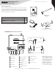
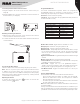
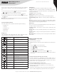
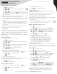
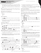
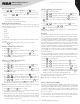
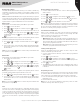
Table Of Contents

2
Copyright © 2021 RCA Communications Systems www.RCACommunicationsSystems.com
Communications Systems
INSTRUCTION MANUAL
RDR2750 Digital Base
Station Radio
PRODUCT INSPECTION
Prior to unpacking the RDR2750 digital base station radio, please
inspect the packaging for signs of damage and report any damage
or missing components immediately to your RCA Communications
System Sales and Service Center. Every RDR2750 digital base station
should come with the following items:
Item Qty.
RDR2750
-Base Station Radio 1
ANB2750U - Antenna for UHF Models
ANB2750V - Antenna for VHF Models
1
MB2750KIT - Mounting Bracket Screw Kit 1
MB2750KIT
Mounting Bracket Screw KitPower Supply
MENU
P1
PTPT TT
CH+ VOL+
CH- VOL-
P2
OK
BACK
RDR2750
Base Station Radio
ANB2750V/U
Antenna
RCA RDR2750 Base Station Overview
1 LCD Display 7 Push-To-Talk Button 13
External Microphone
Jack
2 LED Indicators 8 Internal Speaker 14 Power On / O Switch
3 Menu Button 9
P1 / P2 Buttons
(Programmable)
15
Power Supply
Connector
4 Ok Button 10
Channel Up / Down
Buttons
16 Antenna Connector
5 Back Button 11
Volume Up / Down
Buttons
6 Internal Microphone 12
Programming Cable
Port
Note: The frequency band
of your RDR2750 is marked
on the radio label. If it is not
visible, identify the frequency
band according to the color
code ring on the antenna:
red indicates UHF 400-
430 Mhz, orange indicates
UHF 440-470 Mhz, purple
indicates VHF 136-174 Mhz.
MENU
P1
PTPT TT
CH+ VOL+
CH- VOL-
P2
OK
BACK
3 4 5 6 7
9
8
10
11
1
2
12 13
14 15 16