Operating instructions 88003RC (mode 2) 88004RC (mode 3) RC EYE One Page 3 – 34
These Operating Instructions accompany this product. They contain important information on setting up and using the device. You should refer to these instructions, even if you are buying this product for someone else. Please retain these Operating Instructions for future use! A list of the contents can be found in the Table of contents, with the corresponding page number, on page 3.
TABLE OF CONTENTS 1..Introduction................................................................................................................................................. 4 2..Intended use .............................................................................................................................................. 5 3..Delivery content.......................................................................................................................................... 5 4..
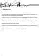
1. INTRODUCTION Dear customer, Thank you for making the excellent decision to purchase this RC Logger® product. You now have a highquality product with a name that represents outstanding products. This product complies with the applicable National and European standards and regulations. We kindly request the user to follow the operating instructions, to preserve this condition and to ensure safe operation! These operating instructions relate to this product.
2. INTENDED USE The model “RC EYE one” is a model helicopter solely designed for private use in the model making area and the operating times associated with this. This system is not suitable for other types of use. Any use other than the one described above damages the device. Moreover, this involves dangers such as short circuit, fire, electric shock, etc. Observe the safety information under all circumstances! The product must not become damp or wet.
-- has been stored for extended periods in poor ambient conditions or -- has been subjected to any serious transport-related stresses. >> Handle the product carefully. Jolts, impacts or a fall even from a low height can damage the product. Before commissioning >> Make sure that no other models are operated on the same channel (transmitter frequency) within the range of the remote control. This applies for all products operated at 915 MHz (e.g. weather stations, radio headphones, etc.).
>> In the event of a crash, the throttle should be immediately reduced to zero. Rotating rotors may be damaged if they come into contact with obstacles e.g. overcharging. Before flying again, these should be checked for possible tears or breakages! >> To avoid damage to the “RC EYE One” helicopter through crashing due to low voltage of the rechargeable battery through total discharge, we recommend that you respect the low voltage light signals without fail.
>> Remove the LiPo flight battery that is to be charged from the model and place it on a fire-proof support (e.g. a plate). Keep a distance to flammable objects (use USB extension cable if required). >> As the charger and the rechargeable LiPo flight battery both heat up during the charging procedure, it is necessary to ensure sufficient ventilation. Never cover the charger or the LiPo flight battery! Of course, this also applies for all other chargers and rechargeable batteries.
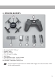
6. OPERATING ELEMENTS 1. Pre-assembled “RC EYE one” 2. Remote Control 3. USB LiPo Charger 4. 7.4 V 350 mAh LiPo Battery 5. AAA Battery 6. Two replacement rotors, counter-clockwise 7. Two replacement rotors, clockwise Not displayed: Replacement Landing Skid The spare part list can be found on our website www.rclogger.com in the Accessories section for the respective product.
7. START PREPARATIONS Inserting batteries in the transmitter 1. Remove the battery compartment lid (1) of the transmitter. You need to push the lever (2) down slightly for this. 2. Insert two micro/AAA size batteries with the correct polarity (3). Observe the corresponding icons in the battery compartment. Insert the battery compartment lid again. Operation of the transmitter with rechargeable batteries is not recommended because of the lower cell voltage (battery = 1.5 V, rechargeable battery = 1.
Charging the flight battery Do not use any computer or notebook USB port to connect power to the USB charger because it may be damaged. USB ports also usually are limited to a current of max. 500 mA. Only use the battery included or the supplementary battery from 89029RC. 1. Use a suitable plug-in mains adapter or a cigarette lighter adapter with one USB output socket each (output 5 V/DC, at least 1.5 A). 2.
Individual battery cells of a battery pack are usually different. The USB charger has two separate chargers integrated. Therefore, it is possible that a battery cell is already charged (LED off) and the other battery cell is still being charged (LED on). Wait until both LEDs have gone out before unplugging the battery. The plug at the flight battery must be connected in a special manner. Therefore, the flight battery cannot be charged with conventional LiPo chargers.
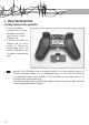
88004RC (mode 3) Transmitter 1. Button on/off 2. Button for channel selection 3. Control stick right (throttle and rudder) 4. Roll trimming 5. Control stick left (roll and nick) 6. Nick trimming 3 5 6 4 2 1 Model Top 1. Rotors front (red rotors) 2. Rotors rear (black rotors) 3.
Model Bottom 1. Button to select the flight modes 2. Hook-and-loop tape for battery fastening 3. Connection socket for flight battery 4. Battery holder 9. SAFETY INSTALLATION The “RC EYE One” has a range of safety devices in the transmitter and model which protect the model from damage and/or should reduce possible damage to a minimum. The protection mechanisms are identified by LED indicators (model) or an acoustic warning signal (transmitter).
>> If there is any interference with reception, the LED is continually lit in the colour of the set flight mode. If reception interferences are permanently present in flight operation, the motors are switched off after approx. five seconds (emergency landing initiated). >> Short-term reception interferences are ignored by the “RC EYE One” by the last control signals of the transmitter retaining the last flight condition in connection with the integrated sensors.
Figure 1a Figure 1b 16
88003RC (mode 2) rudder Rudder denotes the rotation of the “RC EYE One” around the rudder axis (vertical axis). This movement either occurs unintentionally due to the speed torque of the rotors or intentionally as a flight direction change. For the “RC EYE One”, this movement is not controlled by a tail rotor, but through speed variation of the individual rotors to each other. The two red rotors show “front”. If you move the left control lever (figure 2a) to the left, the RC EYE One will turn to the left.
Figure 2b 88003RC (mode 2) nick Nick denotes the movement around the cross axis which can be compared to the nodding of a head. Through this, the “RC EYE One” gains flight speed forwards or backwards or decelerates. The two red rotors show “front”. If you move the right control lever (figure 3a) to the front, the RC EYE One will float forwards as a whole. If you move the control lever to the rear, the RC EYE One will float backwards.
Figure 3a Figure 3b 19
88003RC (mode 2) roll Roll denotes the movement around the centre line which can be compared to the sideways rolling of a ball (or the sideways crawl of a crab). In this way, through lifting one side the “RC EYE One” moves independent of its forward direction to the side. The two red rotors show “front”. If you move the right control lever (figure 4a) to the left, the RC EYE One will float to the left as a whole. If you move the control lever to the right, the RC EYE One will float to the right.
Figure 4b 88004RC (mode 3) hover Flight Hovering denotes a flight status in which the “RC EYE One” neither rises nor falls so that the upwards directed uplift force is equal to the downwards directed weight. This is achieved about at the central throttle position. Push the throttle lever (figure 5a) forward to increase the motor speed and lift up the RC EYE One. Pulling the throttle lever back causes the RC EYE One to drop. Pulling the throttle lever back all the way shuts off the engines.
Figure 5a Figure 5b 22
88004RC (mode 3) rudder Rudder denotes the rotation of the “RC EYE One” around the rudder axis (vertical axis). This movement either occurs unintentionally due to the speed torque of the rotors or intentionally as a flight direction change. For the “RC EYE One”, this movement is not controlled by a tail rotor, but through speed variation of the individual rotors to each other. The two red rotors show “front”. If you move the right control lever (figure 6a) to the left, the RC EYE One will turn to the left.
Figure 6b 88004RC (mode 3) nick Nick denotes the movement around the cross axis which can be compared to the nodding of a head. Through this, the “RC EYE One” gains flight speed forwards or backwards or decelerates. The two red rotors show “front”. If you move the left control lever (figure 7a) to the front, the RC EYE One will float forwards as a whole. If you move the control lever to the rear, the RC EYE One will float backwards.
Figure 7a Figure 7b 25
88004RC (mode 3) roll Roll denotes the movement around the centre line which can be compared to the sideways rolling of a ball (or the sideways crawl of a crab). In this way, through lifting one side the “RC EYE One” moves independent of its forward direction to the side. The two red rotors show “front”. If you move the left control lever (figure 8a) to the left, the RC EYE One will float to the left as a whole. If you move the control lever to the right, the RC EYE One will float to the right.
Figure 8b Flight Mode The “RC EYE One” permits you to choose between three different flight modes depending on your experience. The button for this is at the bottom of the RC EYE One.
>> LED flashes red = expert mode = no limitation to control commands In beginner mode, the control commands are limited to permit you learning how to fly the “RC EYE One” very quickly and easily. This flight mode is recommended for pilots who have no or only very little flight experience with helicopters or QuadroCopters yet. The beginner’s mode is the basic configuration after each battery change.
1. Switch off the remote control transmitter by pushing the on/off button. The transmitter confirms this with a double sound. 2. Put the throttle lever all the way back (engines out). 3. Resets the trims at the transmitter to “0”.
11. To land the “RC EYE One” again, decrease the throttle slightly until the “RC EYE One” gravitates to the ground. A somewhat solid touchdown on the ground is no problem and should not be corrected with jerky throttle movements. Try to touch down where possible in vertical position (“helicopter landing”). Avoid landing with high horizontal speeds (“airplane landing”). 12. After landing, turn off the motors (pull back the throttle lever). 13.
1. Switch off the transmitter. 2. Push the button for channel selection for more than three seconds. A sound signal is emitted. The number of sound signals indicates the transmitter channel number. A sound signal means transmitter channel 1, two sounds signals mean transmitter channel 2, etc. 3. Now release the button. Then push the button repeatedly until the desired transmitter channel (e.g. 3 sound signals = transmitter channel 3) is set. 4.
L R R L 2. For reference, put the “RC EYE One” onto your work surface with the model LED (see arrow) pointing to the front right. 3. The front motors (motor 1 and 2) are at the “front” for this model and must have red rotors. Motor 1 turns counter clockwise, motor 2 turns clockwise. 4. The rear motors (motor 3 and 4) must have black rotors. Motor 3 turns clockwise, motor 4 turns counter clockwise. 5. Do not bend the motor shafts. Bent motor shafts (e.g.
Batteries / rechargeable batteries The user is legally obliged (battery regulation) to return used batteries and rechargeable batteries. Disposing used batteries in the household waste is prohibited! Batteries/ rechargeable batteries containing hazardous substances are marked with the crossed-out wheeled bin. The symbol indicates that the product is forbidden to be disposed via the domestic refuse. The chemical symbols for the respective hazardous substances are Cd = Cadmium, Hg = Mercury, Pb = Lead.
>> >> >> >> Reorient or relocate the receiving antenna. Increase the separation between the equipment and receiver. Connect the equipment into an outlet on a circuit different from that to which the receiver is connected. Consult the dealer or an experienced radio/TV technician for help. The compliance statement for this product is available at “www.rclogger.com”. 17. PRODUCT SUPPORT Visit “http://www.rclogger.com/index.php/contact-us” or call +852 2559 2662 for product support. 18.
Legal notice These operating instructions are published by CEI Conrad Electronic International (HK) Limited, 28th Floor & 2903-9, Pacific Plaza, 418 Des Voeux Road West, Hong Kong. All rights including translation reserved. Reproduction by any method, e.g. photocopy, microfilming, or the capture in electronic data processing systems require the prior written approval by the editor. Reprinting, also in part, is prohibited.