
User manual T98
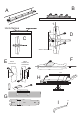
Use the included pushrods (carbon rod 1,8x50 mm) with ball links on both ends. Screw ball links to
the servo arm and control horn using M1,6x4 mm screws. Trim the lenght of carbon rod to sleeve it
into ball links about 5mm deep. Check neutral position of servo and aileron and glue together pushrod
and ball links using thin CA.
Diagram L
Use medium CA to glue the firewall. Attach the upper fuselage part to the backbone using thin or
medium CA.
Diagram M
Assebmle tail wheel as indicated and glue it to the bottom rudder hinge (12mm wide with slots for the
tail wheel). Take the second part of the hinge (16mm wide) and screw both parts together using M2x5
mm screw. Prepare the upper hinge. Cut two slots in the rudder according to the diagram and glue in
hinges using CA. Cut matching slots in fuselage. Make sure that the rudder throws are sufficient and
apply some CA glue over the hinges.
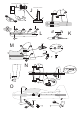
Diagram N
Glue SFGs to the wing. SFGs are not symmetrical – shorter part should be on the bottom side of the
wing. Make sure SFGs are parallel to the fuselage.
The elavator servo is on the side of the backbone right bellow the carbon strip behind the aileron. Use
sharp knife to cut appropriate slot. Take carbon tube 2/1x500 mm and glue metal Z bend into the tube
(let the Z bend stick out about 10-15mm). Sleeve elevator horn on the Z bend and glue the horn into
the slot in the elevator as indicated. Center the servo (servo arm should be heading 12 o’clock). Sleeve
the pushrod support (orange plastic tube 3/2x15mm) on the pushrod. Install the other Z bend into the
servo arm and trim lenght of the pushrod to leave about 10-15mm gap between carbon tube and servo
arm. Use CA to glue Z bend into the tube and check elevator deflection. Install longer servo arm if
necessary. When you are happy with results glue the pushrod support to the fuselage.
Diagram O
Instal rudder servo according to the diagram. On the side of the control horn, tie the control line to the
outer hole. Use small drop of CA to secure the knot and prevent the (rather sharp edged) control horn
from cutting through the line. CA glue the extension arms to your original servo arms and secure with
few threads of the kevlar line and a drop of CA glue. Finally, thread in the included M2x5 screw and
use it to pinch the line in the right
position and with moderate tension. The line should lead around the outside of the screw below the
servo arm first – please refer to the diagram.
Or you can use your own preferred method to attach the cable to the servo.
Motor mount
First attach the „X“ motor mount to the motor using M3x6 socked head bolts. Than screw the „X“
mount to the firewall using 2,9x9mm wood screws.
Final setup and flying
We expect that you know how to connect the receiver to the ESC and to the servos, the ESC to the
motor etc. If not, please refer to the respective instructions or better ask some more experienced friend.
For first flights, your C of G should be 100 mm behind the leading edge at the wing root. Attach your
battery to the plane using adhesive velcro tape for the first flights, to be able to adjust the CG easily.
Set control throws at 60% of max and 30% of exponential on all controls (if your radio permits).
Check all systems and go fly. To trim the plane correctly, the weather should not be too windy.. First,
trim all controls coarsely to make the plane appear to fly straight. You should need about the same
amount of elevator for both inverted and normal flight. You may try vertical power off dive to trim the