
Instruction manual


Fi d b b il & h B il M l
Fi
nne
d
co
pp
er tu
b
e gas
b
o
il
ers
&
water
h
eaters –
B
o
il
er
M
anua
l
8
F
F
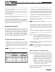
Figure 6 Vertical combustion air and venting, metal chimney system shown
Locate exhaust terminal downwind from air intake to reduce potential for fl ue gas recirculation.
Figure 7 Combination air intake and venting, masonry chimney shown
10 FT 3.1 m
4 FT
1.2 m
5 FT
1.5 m
1.5 FT
0.5 m
5 1/2 FT
1.7 m
1.5 FT .5m
10 FT 3.1 m
3 FT 1 m