
Instruction manual


Fi d b b il & h B il M l
Fi
nne
d
co
pp
er tu
b
e gas
b
o
il
ers
&
water
h
eaters –
B
o
il
er
M
anua
l
15
F
F
Pump Requirements (Primary/Secondary)
is low mass boiler requires a continuous minimum water ow
for proper operation. e boiler pump must be sized to overcome
the head loss of the boiler and the near piping in order to achieve
the required temperature rise. Table 7 provides the heat exchanger
pressure drop and temperature rise gures. e temperature rise
across the boiler must never exceed 35°F, 19.4°C.
A temperature rise outside of the range listed in Table
7 indicates that the ow rate through the heat exchanger
is incorrect which will damage the heat exchanger
voiding the warranty! e maximum allowable
temperature rise is 35°F, 19.4°C.
e maximum allowable ow rate through a LCD
boiler with copper heat exchanger is 92 GPM,
5.8 L/s on 225-1200 models and 115 GPM,
7.3 L/s on 1480 to 2300 models. e cupro-nickel
heat exchanger allows for 100 GPM, 6.3 L/s on 225
to 1200 models and 125 GPM, 7.9 L/s on 1480 to
2300 models.
Low Water Cuto
If a boiler is installed above any radiation elements it must be ed
with a low water cuto device.
Refer to wiring diagram supplied with the boiler/water heater for
proper wiring connections.
Expansion Tank & Air Separator
An expansion tank or other means to control thermal expansion
must be installed in the heating system. An expansion tank must
be installed close to the boiler on the suction side of the pump. An
air scoop and automatic air vent must also be installed to eliminate
air trapped in the system.
Primary/Secondary Piping
Boilers connected to heating systems using zone valves, zone pumps,
or systems that have excessive ow rates or return water temperatures
less than 125°F, 52°C must be isolated from these systems to protect
the boiler.
Variable Water Flows
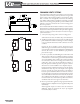
Figure 11 shows a typical primary/secondary piping system. A
dedicated pump is used to maintain a constant water ow through
the boiler. is boiler pump is sized to overcome the head loss of
the boiler and near piping while supplying the ow rate required
to maintain the desired temperature rise across the boiler heat
exchanger. e system pump is sized to provide the required ow
to the heating system.
Low Return Water Temperatures
To prevent the problems associated with condensation of the
products of combustion due to low return water temperatures a
primary/secondary piping system with a bypass and bypass valve
must be installed, see Figure 12 and 12A. e bypass and bypass
valve must be sized the same as the boiler piping. A balancing valve
must also be installed in the supply side of the boiler piping
downstream of the bypass. e balancing valve should be adjusted
to divert some of the heated discharge water into the return water
until the required inlet water temperature is achieved. e primary
and secondary pumps should be sized to provide the required ow
through each system.
Multiple Boiler Systems
Systems using multiple boilers can also be installed using a primary/
secondary manifold system, Figure 13.
Piping For Use With Cooling Units
e boiler, when used in connection with a refrigeration system,
must be installed so the chilled medium is piped in parallel with
the boiler. Appropriate valves must be used to prevent the chilled
water from entering the boiler.
When a boiler is connected to a heating coil that may
be exposed to refrigerated air from an air handling device, the piping
system must be equipped with ow-control valves or some other
automatic means of preventing gravity circulation of the boiler water
during the cooling cycle.