
Instruction manual


Fi d b b il & h B il M l
Fi
nne
d
co
pp
er tu
b
e gas
b
o
il
ers
&
water
h
eaters –
B
o
il
er
M
anua
l
14
F
F
Freeze Protection
is boiler/water heater is CSA designed certi ed for outdoor
installation. Outdoor installations in areas where the danger of
freezing exists are not recommended unless proper freeze protection
is provided. If the unit is to be installed in such an area the following
precautions MUST be observed:
1. A continuous ow of water through the boiler/water heater
MUST be maintained! e pump responsible for ow through
the boiler/water heater must run continuously!
2. An ethylene glycol/water mixture suitable for the minimum
temperature that the unit will be exposed to must be used. e
pump must be capable of producing 15% more ow and
overcoming a 20% increase in head loss. Domestic water systems
must be isolated from the water heater by the use of a heat
exchanger or other approved method.
3. If the boiler/water heater must be shut o for any reason the
electric, gas and water supplies MUST be shut o and the unit
and its pump completely drained.
Improper outdoor installation of this boiler/water heater
can cause boiler failure voiding the manufacturer's
warranty!
Relief Valve
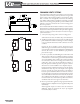
Pipe the discharge of the pressure relief valve to prevent
scalding in the event of a discharge, see Figure 10. The
discharge piping must be sized the same as the pressure
relief valve outlet and installed to allow complete drainage
of both the relief valve and the discharge piping.
Figure 10 Relief valve piping
Never install any type of valve between the boiler/
water heater and the relief valve or an explosion causing
extensive property damage, severe personal injury or
death may occur!
Flow Switch
e ow switch supplied with the boiler/water heater must be wired
to the terminal strip in the control panel to prevent the boiler from
ring unless there’s adequate water ow through the unit. e ow
switch must be installed in the supply piping adjacent to the boiler
outlet connection.
Failure to properly install the ow switch may result
in damage to the boiler/water heater heat exchanger
voiding the warranty!
HEATING SYSTEM PIPING
General Piping Requirements
All heating system piping must be installed by a quali ed technician
in accordance with the latest revision of the ANSI/ASME Boiler
and Pressure Vessel Code, Section IV, and when required, ANSI/
ASME CSD-1, Standard for Controls and Safety Devices for
Automatically Fired Boilers. All applicable local codes and ordinances
must also be followed. A minimum clearance of 1 in, 25 mm must
be maintained between heating system pipes and all combustible
construction. All heating system piping must be supported by suitable
hangers not the boiler.
e thermal expansion of the system must be considered when
supporting the system. A minimum system pressure of 12 psig,
82.7 kPa must be maintained.
Heating Boiler Piping Connections
e supply and return piping should be sized to suit the system.
e supply and return connection sizes are listed in Table 8.
Table 8 Supply & return connection sizes
Model Size Supply Size Return Size
225 thru 300 1 1/2” NPT 1 1/2” NPT
400 thru 2300 2 1/2” NPT 2 1/2” NPT