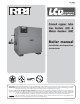
LCD-I0M-6 82-0278 Finned copper tube Gas boilers (LB) & Water heaters (LW) Boiler manual Installation and operation instructions This manual is intended only for use by a qualified heating installer/technician. Read and follow this manual, all supplements and related instructional information provided with the boiler. Install, start and service the boiler only in the sequence and methods given in these instructions.
Fi Finned F d copper tube b gas boilers b il & water heaters h – Boiler B il Manual M l If the information in this manual is not followed exactly, a fire or explosion may result causing property, personal injury or loss of life. Do not store or use gasoline or other flammable vapors and liquids in the vicinity of this or any other appliance WHAT TO DO IF YOU SMELL GAS: • Do not try to light any appliance. BEFORE YOUR START. . . . . . . . . . . . . . . . . PAGE 2 RATINGS & CAPACITIES . . . . . . . . . . .
Fi Finned F d copper tube b gas boilers b il & water heaters h – Boiler B il Manual M l In Canada, the installation must be in accordance with the requirements of CSA B149.1 or .2, Installation Code for Gas Burning Appliances and Equipment. If installed in the Commonwealth of Massachusetts, you MUST FOLLOW the additional instructions located in the back of this manual (MACODE-3). The owner should maintain a record of all service work performed with the date and a description of the work done.
Fi Finned F d copper tube b gas boilers b il & water heaters h – Boiler B il Manual M l Combustion air contaminated with fluorocarbons or other halogenated compounds such as cleaning solvents and refrigerants will result in the formation of acids in the combustion chamber.
Fi Finned F d copper tube b gas boilers b il & water heaters h – Boiler B il Manual M l Figure 2 Vertical venting using a masonry chimney system and inside air Figure 3 Horizontal venting using inside air 1/4 IN. PER F00T 20 mm/m 1.5 FT 0.5 m Table 2 VENT PIPE DIAMETER IN.
Fi Finned F d copper tube b gas boilers b il & water heaters h – Boiler B il Manual M l All Air From Outside The Building Intake Air Option - General Guidelines When installed in a confined space without utilizing the intake air option two permanent openings communicating directly with, or by ducts to, the outdoors or spaces that freely communicate with the outdoors must be present. The upper opening must be within 12 in, 305 mm of, but not less than 3 in, 76 mm from, the top of the enclosure.
Fi Finned F d copper tube b gas boilers b il & water heaters h – Boiler B il Manual M l Figure 4 Horizontal combustion air and venting for a single unit 9 Vertical Distance, Y 8 7 6 2000 & Larger 5 1201 To 2000 4 901 To 1200 200 To 900 3 2 1000 BTU'S 1 0 0 5 10 15 20 Horizontal Distance , X When running horizontal combustion air and venting for single or multiple units, exhaust and combustion air terminals must be installed on the same plane (outside wall) in order to prevent pressure diff
Fi Finned F d copper tube b gas boilers b il & water heaters h – Boiler B il Manual M l Vertical combustion air and venting, metal chimney system shown Locate exhaust terminal downwind from air intake to reduce potential for flue gas recirculation. Figure 6 10 FT 3.1 m 4 FT 1.2 m 5 1/2 FT 1.7 m 1.5 FT 0.5 m 5 FT 1.5 m Combination air intake and venting, masonry chimney shown Figure 7 10 FT 3.1 m 3 FT 1 m 1.5 FT .
Fi Finned F d copper tube b gas boilers b il & water heaters h – Boiler B il Manual M l GENERAL VENTING GUIDELINES The vent installation must be in accordance with Part 7, Venting of Equipment, of the National Fuel Gas Code, ANSI Z223.1/NFPA 54-latest revision or applicable provisions of the local building codes. Canadian installations must comply with CSA B149.1 or .2 Installation Code.
Fi Finned F d copper tube b gas boilers b il & water heaters h – Boiler B il Manual M l VERTICAL/CHIMNEY VENTING The LCD is listed as a Category I appliance when vented vertically into a metal chimney system or properly sized masonry chimney, Figures 1, 2, 6 & 7. The chimney must provide a negative pressure of 0.01 to 0.08 in, .25 to 2.0 mm WC at the boiler/water heater flue collar with the unit running at full load. A barometric damper must be installed between the flue collar and the vent connector.
Fi Finned F d copper tube b gas boilers b il & water heaters h – Boiler B il Manual M l Horizontal vent systems shall terminate at least 4 ft, 1.2 m below, 4 ft, 1.2 m horizontally from or 1 ft, 0.23 m above any door, window or gravity air inlet into any building. It must not terminate less than 4 ft, 1.2 m horizontally from, and in no case above or below, unless a 4 ft, 1.2 m horizontal distance is maintained, from electric meters, gas meters, regulators and relief equipment and not less than 7 ft, 2.
Fi Finned F d copper tube b gas boilers b il & water heaters h – Boiler B il Manual M l Figure 8 Outdoor venting COMMON VENT SYSTEMS If an existing boiler/water heater is removed from a common venting system, the common venting system may then be too large for the proper venting of the remaining appliances connected to it.
Fi Finned F d copper tube b gas boilers b il & water heaters h – Boiler B il Manual M l e) Test for spillage at the draft hood relief opening after 5 minutes of main burner operation. Use the flame of a match or candle, or smoke from a cigarette, cigar or pipe. Faire fonctionner le brûleur principal pendant 5 min ensuite, déterminer si le coupe-tirage déborde à l'ouverture de décharge. Utiliser la flamme d'une allunette ou d'une chandelle ou la fumée d'une cigarette, d'un cigare ou d'une pipe.
Fi Finned F d copper tube b gas boilers b il & water heaters h – Boiler B il Manual M l Freeze Protection Flow Switch This boiler/water heater is CSA designed certified for outdoor installation. Outdoor installations in areas where the danger of freezing exists are not recommended unless proper freeze protection is provided. If the unit is to be installed in such an area the following precautions MUST be observed: 1.
Fi Finned F d copper tube b gas boilers b il & water heaters h – Boiler B il Manual M l Pump Requirements (Primary/Secondary) Variable Water Flows This low mass boiler requires a continuous minimum water flow for proper operation. The boiler pump must be sized to overcome the head loss of the boiler and the near piping in order to achieve the required temperature rise. Table 7 provides the heat exchanger pressure drop and temperature rise figures.
Fi Finned F d copper tube b gas boilers b il & water heaters h – Boiler B il Manual M l Figure 11 Typical primary/secondary piping system (See notes) Pump Gate Valve Globe Valve Angle Valve NOTES: Bufferfly Valve 1. Boiler circuit piping must be sized large enough to handle maximum flow through unit. 2. Boiler pump sized to boiler design flow requirements. 3. All boilers furnished with factory mounted outlet water temperature gauge. 4. Boiler pump purging required. Use terminals supplied.
Fi Finned F d copper tube b gas boilers b il & water heaters h – Boiler B il Manual M l Figure 12A Low temperature piping with thermostatic valve (See notes and adjustment procedures) Pump Gate Valve Globe Valve Angle Valve NOTES: 1. For pump selection consult factory. 2. Boiler pump sized to boiler and thermostatic 3-way valve design flow requirements. 3. Boiler circuit piping must be sized large enough to handle maximum flow through unit. 4.
Fi Finned F d copper tube b gas boilers b il & water heaters h – Boiler B il Manual M l DOMESTIC WATER SUPPLY PIPING Proper control settings must be used to prevent water supplied for domestic use from exceeding 130°F, 54°C or a scald injury will occur! When higher water temperatures are required for appliances such as a dishwasher, a mixing valve or some other tempering means must be installed. Households with small children may require water temperatures less than 120°F, 49°C.
Fi Finned F d copper tube b gas boilers b il & water heaters h – Boiler B il Manual M l Table 9A LCD Heat exchanger selection graph Table 9B LCD Pumping performance requirement 19
Fi Finned F d copper tube b gas boilers b il & water heaters h – Boiler B il Manual M l Figure 14 Typical water heating piping (LW models only) (See notes) 3 1 Pump 8 4 Pressure Relief Valve Valve 7 Globe Valve Flow Switch 2 Angle Valve D-1 Rev 6 Bufferfly Valve Attention: Not all RBI stock storage tanks incorporate this tapping: See Note 1.
Fi Finned F d copper tube b gas boilers b il & water heaters h – Boiler B il Manual M l GAS SUPPLY PIPING Check the boiler/water heater rating plate to make sure that the boiler/water heater is for the type of gas that will be used. If it isn’t, do not connect the boiler/ water heater to the gas supply. Gas supply piping must be in accordance with the National Fuel code, ANSI Z223.1-latest revision or applicable provisions of the local building codes. Canadian installations must comply with CAN/CGA B149.
Fi Finned F d copper tube b gas boilers b il & water heaters h – Boiler B il Manual M l ELECTRICAL WIRING GENERAL OPERATION Electrical Power Connections Label all wires prior to disconnection when servicing controls. Wiring errors can cause improper and dangerous operation! Verify proper operation after servicing. Au moment de l'entretien des commandes, étiquetez tous les fils avant de les débrancher. Des erreurs de câblage peuvent entraîner un fonctionnement inadéquat et dangereux.
Fi Finned F d copper tube b gas boilers b il & water heaters h – Boiler B il Manual M l BOILER/WATER HEATER OPERATION Figure 17 Pressure switch tap(s) Staging Operation The LCD boiler/water heater series is separated into on/off and 2-stage units depending on the model selected. The 225-400 models have on/off staging, while the 600 through 2300 models have a two stage option. Input staging is controlled from an aquastat controller that signals the relays to select the blower and gas valve modes.
Fi Finned F d copper tube b gas boilers b il & water heaters h – Boiler B il Manual M l Table 18 Low air condition action, L225-L2300 Stage 1 Control Action No Power to Flame Sense Module Table 19 Low air condition action, L600-L2300 Stage 1 2 Control Action No Power to Flame Sense Module No Power to Flame Sense Module 4. If the pilot flame isn’t sensed, the FSM de-energizes the PV terminal and waits 5 minutes before initiating the second ignition trial.
Fi Finned F d copper tube b gas boilers b il & water heaters h – Boiler B il Manual M l OPERATION SEQUENCE, 2 STAGE OPTION L600 THROUGH L2300 Refer to the wiring diagram included with the unit for further control system info. POWER ON: Demand for Heat: 1. The low operator switch closes, energizing pump delay timer TD4 and the water pump(s). 2. Water flow through the unit closes the water flow switch contacts energizing blower delay timer TD3. 3.
Fi Finned F d copper tube b gas boilers b il & water heaters h – Boiler B il Manual M l OPERATING INSTRUCTIONS FOR YOUR SAFETY READ BEFORE OPERATING POUR VOTRE SÉCURITÉ LISEZ AVANT DE METTRE EN MARCHE A. This appliance is equipped with an ignition device which automatically lights the pilot. Do not try to light the pilot by hand. Cet appareil est muni d’un dispositif d’allumage qui allume automatiquement la veilleuse. Ne tentez pas d’allumer la veilleuse manuellement. B.
Fi Finned F d copper tube b gas boilers b il & water heaters h – Boiler B il Manual M l 13. Turn the knob on the pilot valve to on, Figure 18. 14. Turn on all electric power to the boiler and set the operating control or thermostat to the desired setting. 15. With the unit operating at high purge the differential air pressure should match those listed in Table 15. To adjust the differential air pressure see the “AIRFLOW ADJUSTMENT” instructions in the “CHECKING AND ADJUSTMENTS” section.
Fi Finned F d copper tube b gas boilers b il & water heaters h – Boiler B il Manual M l Instructions De Mise En Marche CHECKING & ADJUSTMENTS 1. ARRÊTEZ! Lisez les instructions de sécurité sur la portion supérieure de cette étiquette. 2. Réglez le thermostat à la température la plus basse. 3. Coupez l’alimentation électrique de l’appareil. 4. Cet appareil est muni d’un dispositif d’allumage qui allume automatiquement la veilleuse. Ne tentez pas d’allumer la veilleuse manuellement. 5.
Fi Finned F d copper tube b gas boilers b il & water heaters h – Boiler B il Manual M l Pilot Adjustment The pilot burner is actually an isolated main burner that’s controlled by a separate pilot valve. Pilot pressure settings are as shown in Table 20. These pressures are measured at the pilot pressure valve, see Figure 19. Tables 13 and 14 above list the firing mode that is associated with each stage. To view the pilot without main burner operation, take the following steps: For L225-L400: 1.
Fi Finned F d copper tube b gas boilers b il & water heaters h – Boiler B il Manual M l CONTROL DESCRIPTION Boiler Thermostat If a thermostat is to be used to control the boiler always follow the instructions included with the thermostat. Proper location of the thermostat will ensure efficient trouble-free operation of the boiler. Mount the thermostat to an inside wall at a height approximately five feet above the floor.
Fi Finned F d copper tube b gas boilers b il & water heaters h – Boiler B il Manual M l MAINTENANCE Disconnect electrical power and close the manual gas shut off valve before performing maintenance or severe personal injury may result! Improper installation, adjustment, alteration, service or maintenance can cause property damage, personal injury, exposure to hazardous materials or loss of life.
Fi Finned F d copper tube b gas boilers b il & water heaters h – Boiler B il Manual M l Heat Exchanger Removal, Cleaning & Replacement - See Figure 20 1. Close the shut off valves in the inlet and outlet piping. On heating systems close the system fill valve and relieve the system pressure from the boiler by carefully lifting the relief valve or opening the drain valve. 2. Drain the boiler/water heater and disconnect it from the system piping. 3. Remove the inlet/outlet and return headers. 4.
Fi Finned F d copper tube b gas boilers b il & water heaters h – Boiler B il Manual M l Figure 21 Heat exchanger upper rail screws 5. The aquastat high limit controls the maximum water temperature in the boiler. It should be set at least 20°F, 11°C above the operater setpoint. If the water temperature reaches the set temperature before the demand for heat has been met, the aquastat high limit should shut the boiler off. The water temperature should never exceed the maximum set point of 240°F, 116°C.
Fi Finned F d copper tube b gas boilers b il & water heaters h – Boiler B il Manual M l TROUBLE-SHOOTING SYMPTOM 1 2 No Power To Control Circiut No Action On Call For Heat CHECK ACTION 1. Power not connected 1. Wire unit to line voltage 2. External circuit breaker open 2. Reset breaker 3. Transformer circuit breaker open 3. Reset breaker 1. Primary limit or other control/interlock open 1.
Fi Finned F d copper tube b gas boilers b il & water heaters h – Boiler B il Manual M l TROUBLE-SHOOTING SYMPTOM 9 Pilot Lights But Main Burners Will Not Fire CHECK ACTION 1. Bad flame sense lead from ignitor to flame sense module 1. Check sense lead & ground connections, adjust as necessary 2. Defective flame sense module 2. Replace flame sense module 3. Manual valve(s) in air plenum closed 3. Remove upper front jacket panel, open manual valve(s) 4. Main valves(s) not wired 4.
Fi Finned F d copper tube b gas boilers b il & water heaters h – Boiler B il Manual M l REPAIR PARTS Figure 23 36 Exploded view
Fi Finned F d copper tube b gas boilers b il & water heaters h – Boiler B il Manual M l REPAIR PARTS (CONTINUED) Model Size with Item Quantities Below Ref # Name of Part 1 Jacket Lower Front Panel Part # 225 300 70-2716 1 1 70-2717 400 600 750 1050 1200 1480 1650 1970 2300 1 70-2718 1 70-2719 1 70-2721 1 70-2722 1 1 70-2723 1 70-2724 1 70-2725 Jacket Lower Front Panel (SS) 70-2716.1 1 1 1 70-2717.1 1 70-2718.1 1 70-2719.1 1 70-2721.1 1 70-2722.1 1 1 70-2723.
Fi Finned F d copper tube b gas boilers b il & water heaters h – Boiler B il Manual M l REPAIR PARTS (CONTINUED) Model Size with Item Quantities Below Ref # Name of Part Part # 225 300 400 1 1 1 600 750 1050 1200 1480 1650 1970 2300 4 Junction Box Assembly 70-3113 Junction Box Assembly 70-3113.
Fi Finned F d copper tube b gas boilers b il & water heaters h – Boiler B il Manual M l REPAIR PARTS (CONTINUED) Model Size with Item Quantities Below Ref # Name of Part Part # 225 300 Jacket Top Panel 03-1801 1 1 11 03-1802 400 600 750 1050 1200 1480 1650 1970 2300 1 03-1803 1 03-1804 1 03-1806 1 03-1807 1 1 03-1808 1 03-1809 1 03-1810 Jacket Top Panel (SS) 03-1801.1 1 1 1 03-1802.1 1 03-1803.1 1 03-1804.1 1 03-1806.1 1 03-1807.1 1 1 03-1808.1 1 03-1809.
Fi Finned F d copper tube b gas boilers b il & water heaters h – Boiler B il Manual M l REPAIR PARTS (CONTINUED) Model Size with Item Quantities Below Ref # Name of Part Part # 225 300 Jacket Base Panel 03-1847 1 1 13 03-1848 400 600 750 1050 1200 1480 1650 1970 2300 1 03-1849 1 03-1850 1 03-1852 1 03-1853 1 1 03-1854 1 03-1855 1 03-1856 Combustion Chamber Base Panel 14 03-1974 1 1 1 03-1975 1 03-1976 1 03-1977 1 03-1979 1 03-1980 1 1 03-1981 1 03-1982 1 03-19
Fi Finned F d copper tube b gas boilers b il & water heaters h – Boiler B il Manual M l REPAIR PARTS (CONTINUED) Model Size with Item Quantities Below Ref # Name of Part Part # 225 300 400 600 1 1 1 1 750 1050 1200 1480 1650 1970 2300 18 Comb Chamber Upper Left Side Panel 70-2770 Comb Chamber Upper Right Side Panel 70-2771 1 1 1 1 1 1 1 19 Heat Exchanger Guide Rail 03-1938 4 4 4 4 4 4 4 20 Combustion Chamber Rear Panel 03-1904 1 1 1 1 03-1905 1 1 1 1 1 1 1 1
Fi Finned F d copper tube b gas boilers b il & water heaters h – Boiler B il Manual M l REPAIR PARTS (CONTINUED) Model Size with Item Quantities Below Ref # Name of Part Part # 225 24, 25, Tile Kit 05-0212 1 05-0202 27 300 400 600 750 1050 1200 1480 1650 1970 2300 1 05-0203 1 05-0204 1 05-0205 1 05-0207 1 05-0208K 1 05-0208 1 05-0209 1 05-0210K 1 05-0211 26 28 1 End Refractory Panel, Right 05-0058 1 1 1 1 1 1 1 1 1 1 1 End Refractory Panel, Left 05-0107 1 1 1
Fi Finned F d copper tube b gas boilers b il & water heaters h – Boiler B il Manual M l REPAIR PARTS (CONTINUED) Model Size with Item Quantities Below Ref # Name of Part NS Burner Support Rail Part # 225 300 03-2090 1 1 03-2091 400 600 750 1050 1200 1480 1650 1970 2300 1 03-2092 1 03-2093 1 03-2095 1 03-2096 1 03-2097 1 1 03-2098 1 03-2099 1 31 Spark Ignitor (*prior to 0205 - must order cable 44-0056) 16-0327* 1 1 1 1 1 1 1 1 1 1 1 NS Ignition Cable Assembly 44-00
Fi Finned F d copper tube b gas boilers b il & water heaters h – Boiler B il Manual M l REPAIR PARTS (CONTINUED) Model Size with Item Quantities Below Ref # Name of Part Heat Exchanger Assembly (Cupronickel) NS (Cast Iron Headers) Part # 225 300 70-3012 1 1 70-3013 400 600 750 1050 1200 1480 1650 1970 2300 1 70-3014 1 70-3015 1 70-3017 1 70-3018 1 70-2842 1 70-2843 1 70-2844 1 70-2845 Heat Exchanger Assembly (Cupronickel) (Bronze Headers) 70-3034 1 1 1 70-3035 1 70-3036 1
Fi Finned F d copper tube b gas boilers b il & water heaters h – Boiler B il Manual M l REPAIR PARTS (CONTINUED) Model Size with Item Quantities Below Ref # Name of Part Part # 225 300 400 600 2 3 3 3 34 V Baffle Hold-Down 03-2021 NS Heat Exchanger Support Channel 03-2022 750 1050 1200 1480 1650 1970 2300 4 4 5 5 8 8 1 03-2023 1 03-2024 35 Tube Replacement Assembly 70-3080 8 1 2 2 70-3081 2 70-3082 2 70-3083 2 70-3085 2 70-3086 2 36 O Ring, Inlet/Outlet & Return He
Fi Finned F d copper tube b gas boilers b il & water heaters h – Boiler B il Manual M l REPAIR PARTS (CONTINUED) Model Size with Item Quantities Below Ref # Name of Part Part # 225 300 400 Firing Valve, 3/4" 11-0461 1 1 1 Firing Valve, 1" 11-0456 Firing Valve, 1-1/4" 11-0457 45 2 11-0458 Firing Valve, 2" 11-0459 NS Manual Pilot “B” Valve 11-0031 1 1 1 46 Main Gas Valve, VR8304 11-0056 1 1 1 Main Gas Valve, V8944B, 1" 11-0171 Main Gas Valve, V8944B, 1-1/4" 11-0172 47 48
Fi Finned F d copper tube b gas boilers b il & water heaters h – Boiler B il Manual M l REPAIR PARTS (CONTINUED) Model Size with Item Quantities Below Ref # Name of Part 54 Main Board Assembly (On/Off ) Part # 225 300 400 600 750 1050 1200 1480 1650 1970 2300 70-2927 1 1 1 1 1 1 1 1 1 1 1 Main Board Assembly (2-Stage) 70-2928 1 1 1 1 1 1 1 1 NS Main Board 40-0074 1 1 1 1 1 1 1 1 1 1 1 NS Timer Board 40-0075 1 1 1 1 1 1 1 1 1 1 1 NS LED Indicator Bo
Fi Finned F d copper tube b gas boilers b il & water heaters h – Boiler B il Manual M l START UP FORM Date of Start Up: Job Name: Model #: Serial Number #: Boiler Model: Dominator LCD Company Name Fuel Type: Natural Gas Propane Tech Name System Type: Hydronic Domestic Phone Number PRE-START UP CHECK LIST ANY VISUAL DAMAGE TO UNIT? INLET FILTER INSTALLED AND CLEAN? PIPING PROPERLY CONNECTED? ALL WIRING CONNECTED PROPERLY? SYSTEM FLOODED AND FLOWING? BOILER PUMP P
Fi Finned F d copper tube b gas boilers b il & water heaters h – Boiler B il Manual M l COMBUSTION/SAFETY REPORT FACTORY FIRE TEST REPORT: Manifold Gas Pressure: "WC" Air Differential Pressure: "WC" Low Fire FIELD TEST REPORT IN STAGE: Manifold Gas Pressure: "WC" Air Differential Pressure: "WC" Pilot Manifold Pressure: "WC" CO2: Stack Temp. (Net): Efficiency @ °F Inlet Temp.
Fi Finned F d copper tube b gas boilers b il & water heaters h – Boiler B il Manual M l NOTICE! Commonwealth of Massachusetts Installation Requirements In the Commonwealth of Massachusetts, the installation must be performed by a licensed plumber or gas fitter. 1.
LIMITED WARRANTY Boilers/Water Heaters Industrial, Commercial and Other Non-Residential Use The “Manufacturer” warrants to the original owner at the original installation site that the heat exchanger of the Industrial, Commercial, and other Non-Residential Use Boiler (the “Product”) will be free from defects in material or workmanship for ten (10) years from the date of installation. Additional twenty one (21) year thermal shock warranty on heat exchanger.
260 North Elm Street 7555 Tranmere Drive Westfield, MA 01085 Mississauga, Ontario L5S 1L4 Canada Phone: (413) 568-9571 Phone: (905) 670-5888 Fax: (413) 568-9613 Fax: (905) 670-5782 www.rbiwaterheaters.com Copyright 2012 Mestek, Inc.