Distributed by Any reference to Raytheon or RTN in this manual should be interpreted as Raymarine. The names Raytheon and RTN are owned by the Raytheon Company.
ST6000 Plus Autopilot Control Unit Owner’s Handbook Document number: 81133_3 Date: 1st April 1999
2 Title of handbook
1 Preface Raytheon Electronics, as part of its commitment to continuous imrovement and updating, reserve the right to make changes, without prior notice, to the equipment, equipment specifications, and the instructions contained within this handbook. To the best of our knowledge, the information contained within this handbook was correct as it went to press. A great deal of care has been taken to ensure that this handbook is as accurate as possible.
2 ST6000 Plus Autopilot Control Unit Owner,s Handbook
3 Preface Preface This handbook contains information on the operation and installation of your new equipment. In order to obtain the best performance from your autopilot, please read this handbook thoroughly. How this handbook is organised This handbook is divided into the following chapters: Chapter 1: Introduces the autopilot, its features and its use. Chapter 2: Covers basic autopilot operation.
4 ST6000 Plus Autopilot Control Unit Owner,s Handbook The following rules should always be observed: • Maintain a permanent watch and regularly check all around for other vessels and obstacles to navigation – no matter how clear the sea may appear a dangerous situation can develop rapidly. • Maintain an accurate record of the vessel’s position either by use of a radio navigation receiver or visual bearings. • Maintain a continuous plot of position on a current chart.
5 Preface Contents Preface ..................................................................................... 3 How this handbook is organised ....................................... 3 Warranty ............................................................................ 3 Safety information ............................................................. 3 EMC conformance ............................................................ 4 Chapter 1: Introduction ................................................
6 ST6000 Plus Autopilot Control Unit Owner,s Handbook 2.6 Data pages ................................................................. 11 Chapter 3: Advanced Operation ......................................... 13 3.1 Operation in Track mode .......................................... 13 Initiating Track mode ................................................ 13 Automatic acquisition .......................................... 14 Manual acquisition ..............................................
Preface 7 3.3 Adjusting autopilot performance .............................. 23 Changing the response level (AutoSeastate) ............. 23 Changing the rudder gain .......................................... 24 3.4 Alarms ....................................................................... 24 SeaTalk failure ..................................................... 25 No link ................................................................. 25 Off course ....................................................
8 ST6000 Plus Autopilot Control Unit Owner,s Handbook Rudder calibration ..................................................... 36 Data pages ................................................................. 36 5.2 Dealer setup: Type 100/300 Course Computer ......... 38 Recommended settings .............................................. 39 Pilot type ................................................................... 39 Calibration lock .........................................................
Preface 9 6.2 Control head .............................................................. 50 Siting ......................................................................... 51 Mounting procedure .................................................. 51 Connections to the SeaTalk bus ................................. 52 SeaTalk cables ..................................................... 52 Cable types .......................................................... 52 Typical SeaTalk cabling ......................
10 ST6000 Plus Autopilot Control Unit Owner,s Handbook Checking autopilot operation .................................... 66 Checking the rudder gain .......................................... 66 Chapter 8: Maintenance ...................................................... 69 General ............................................................................ 69 Servicing and safety ........................................................ 69 Advice ..........................................................
Chapter 1: Introduction 1 Chapter 1: Introduction 1.1 Overview The ST6000 Plus is a SeaTalk® compatible autopilot control unit. It is designed for use as a repeater in an autopilot system, allowing autopilot control from a secondary location, or as the control unit for a Type 100/300 Course Computer. It can also repeat instrument data in a programmable selection of Data Pages.
2 ST6000 Plus Autopilot Control Unit Owner,s Handbook Setup and calibration options to suit each installation, giving maximum performance with many types of boat, with three calibration menus (user, intermediate and dealer) Raytheon CodeLock security support 1.
3 Chapter 2: Basic Operation Chapter 2: Basic Operation This chapter first provides summary diagrams of the key functions and screen layout. It then gives operating instructions for engaging the autopilot and using Auto mode, changing the lighting, and displaying Data Pages. 2.1 Key functions The autopilot is controlled using simple push-button operations, all of which are confirmed with a beep. In addition to the main single key functions, there are several dual key functions.
4 ST6000 Plus Autopilot Control Unit Owner,s Handbook 2.2 Display layout The following illustration shows all the elements, together with a brief description, that make up the ST6000 Plus autopilot LCD display. MANUAL 3 Rudder or Steer Direction Indicator D3507-1 The bar graph at the bottom of the display is normally a rudder bar.
Chapter 2: Basic Operation 2.3 Using Auto mode Engaging the Autopilot (Auto) 1. Steady the vessel on the required heading. 2. Press auto. In Auto mode, the display shows the locked autopilot heading. Disengaging the autopilot (Standby) to return to hand steering Press standby. In Standby mode, the display shows the vessels current compass heading. The previous autopilot heading is memorised and can be recalled (see Returing to the previous locked heading).
6 ST6000 Plus Autopilot Control Unit Owner,s Handbook Dodging obstacles in Auto mode In order to avoid an obstacle when your vessel is under autopilot control, select a course change in the appropriate direction (for example, port 30° = press –10 three times). When safely clear of the obstacle, you can reverse the previous course change (for example, press +10 three times), or return to the previous locked heading (LAST HDG).
7 Chapter 2: Basic Operation 1. Press auto for 1 second. The previous locked heading (LAST HDG?) is displayed for 10 seconds. 1 Note: A direction-to-steer indicator is displayed to show you the direction the vessel will turn. 2. To accept this heading, and resume the original course, press auto once within this 10 second period. If you do not press auto while the display is flashing, the current heading will be maintained.
8 ST6000 Plus Autopilot Control Unit Owner,s Handbook AutoTack to port Press the -1 and -10 keys together to tack to port . Off course alarm The off course alarm will sound if the locked autopilot heading and the vessels current heading differ for more than 20 seconds, by more than the alarm angle set in calibration (the factory default is 20°).
Chapter 2: Basic Operation 9 1. To cancel the off course alarm, press standby to return to hand steering. 2. Check whether your vessel is carrying too much sail, or whether the sails are badly balanced. Significant improvements in course keeping can usually be obtained by improving sail balance. Operating hints Making major course changes It is sound seamanship to make major course changes only when steering manually.
10 ST6000 Plus Autopilot Control Unit Owner,s Handbook 4. Select auto and let the vessel settle onto course. 5. Bring the vessel to the final course with 1° increments. Sailboats in gusty conditions In gusting conditions, the course may tend to wander slightly, particularly if the sails are badly balanced. A significant improvement in course keeping can always be obtained by improving sail balance.
11 Chapter 2: Basic Operation 1 The display times out to normal operation after 10 seconds of keypad inactivity. Pressing any other key before the 10 second time-out will select the mode assigned to that key (for example, auto selects Auto mode, standby selects Standby mode). Note: If other SeaTalk instruments or autopilot control units are connected to SeaTalk, the illumination can be adjusted from these units. Any adjustments to the illumination are lost when the unit is switched off.
12 ST6000 Plus Autopilot Control Unit Owner,s Handbook Up to 7 Data Pages are available using the disp key. The number of pages, and the information displayed on each page, depends on the the selections made in User Setup (see section 5.1). The following illustration shows the default settings for the Data Pages. D3581-1 If the required data for a page is not available, dashes are displayed instead of a value. Most displays are repeated data, and cannot be adjusted.
Chapter 3: Advanced Operation 13 Chapter 3: Advanced Operation This chapter provides information on: Operation in Track mode Operation in Vane mode (WindTrim) Adjusting the response level and rudder gain Alarms 3.1 Operation in Track mode Track mode is used to maintain a track between two waypoints created on a GPS, Decca, or Loran navigation system. The ST6000 Plus will then compute any course changes to keep your boat on track, automatically compensating for tidal streams and leeway.
14 ST6000 Plus Autopilot Control Unit Owner,s Handbook Automatic acquisition Automatic acquisition can only be achieved if the pilot is receiving cross track error and bearing to waypoint information (via SeaTalk or NMEA 0183). It is initiated as follows: 1. Bring the vessel to within 0.1nm of track 2. Press auto. 3. Press track to enter Track mode, with the current locked heading displayed.
15 Chapter 3: Advanced Operation Previous Heading D3505-1 The display shows the new bearing to waypoint. Manual acquisition For manual track acquisition, when only cross track error data is available: 1. Steer the vessel to within 0.1nm of track. 2. Bring the heading to within 5° of the bearing to the next waypoint. 3. Press auto. 4. Press track to enter Track mode. The display shows the locked pilot heading.
16 ST6000 Plus Autopilot Control Unit Owner,s Handbook Cross track error Cross track error (XTE) is the distance between the current position and a planned route. This is displayed in nautical miles (nm), statute miles (SM) or kilometres, and is taken directly from your navigator. The Large XTE alarm sounds if the XTE exceeds 0.3nm. The direction of the error is identified as Pt port or Stb starboard.
17 Chapter 3: Advanced Operation performance over a wide range of vessel speeds. If speed data is available, the ST6000 Plus uses the measured vessel speed. Otherwise, the Speed Over Ground (SOG) or specified cruise speed is used, depending on the calibration setting (see Dealer Setup in Chapter 5).
18 ST6000 Plus Autopilot Control Unit Owner,s Handbook To accept the new target waypoint, press track. Skipping a waypoint – SeaTalk navigators only If you wish to advance to the next waypoint before you have arrived at the target waypoint, press track for 1 second. The Waypoint Advance information for the next waypoint is displayed. Advance While the waypoint advance alarm is sounding, Track mode is suspended and the ST6000 Plus maintains the current boat heading. 1.
Chapter 3: Advanced Operation 19 Position confirmation at the start of a passage At the start of a passage you must always confirm the fix given by the position transducer, using an easily identifiable fixed object. Check for fixed positional errors and compensate for them. Verifying computed positions Verify the computed position with a dead reckoned position, calculated from the average course steered and the distance logged. Plot frequency In open water, plots should be at least hourly.
20 ST6000 Plus Autopilot Control Unit Owner,s Handbook To use Vane mode, the ST6000 Plus must receive wind information from one of the following sources: SeaTalk Wind instrument, connected to a ST6000 Plus via SeaTalk NMEA wind information Raytheon wind vane connected to a SeaTalk interface box Selecting Vane mode Vane mode can be selected from either Standby or Auto modes, as follows: 1. Steady the vessel onto the required apparent wind angle. 2.
Chapter 3: Advanced Operation 21 Returning to the previous apparent wind angle (LAST WND) If for any reason the vessel is steered away from the selected apparent wind angle (for example, a dodge manoeuvre or selecting Standby) you can return to the previous locked wind angle: 1. Press standby and auto together for 1 second to display the previous apparent wind angle (LAST WND?). 1 The LAST WND? text alternates with the previous wind angle and direction.
22 ST6000 Plus Autopilot Control Unit Owner,s Handbook Wind shift alarm The wind shift alarm sounds, and the text WINDSHIFT is displayed, if a wind shift of more than 15° is detected. 1. Press standby to cancel the alarm and return to hand steering, and steer onto the required heading. 2. Press standby and auto together to return to Vane mode with the new apparent wind angle. Using AutoTack in Vane mode The automatic tack function tacks the vessel through a set angle (the factory default is 100°).
Chapter 3: Advanced Operation 23 Operating hints Major changes to the selected apparent wind angle should be made by returning to Standby mode, changing course manually, then reselecting Vane Mode. Vane mode filters the windvane output. This provides the optimum response for off-shore conditions where genuine shifts in wind direction occur gradually.
24 ST6000 Plus Autopilot Control Unit Owner,s Handbook The response can be changed at any time. To do so: 1. Press the +1 and -1 keys together momentarily to display the RESPONSE screen. 2. Press +1 or -1 to change the response level. 3. Wait for 10 seconds, or press disp , to return to the previous display. D3606-1 Changing the rudder gain Press the +1 and -1 keys together for 1 second to display the Rudder Gain screen, and adjust the setting in the same way as for the response level.
Chapter 3: Advanced Operation 25 SeaTalk failure ST FAIL This silent alarm indicates that there is a wiring fault in the SeaTalk connection. No link NO LINK This silent alarm indicates that there is no link between the ST6000 Plus and the course computer. Off course OFFCOURSE This alarm is activated when the vessel has been off course from the locked heading by more than the specified angle for more than 20 seconds (see section 2.3, Using Auto mode).
26 ST6000 Plus Autopilot Control Unit Owner,s Handbook Data not received NO DATA This alarm is displayed in the following circumstances: Track mode is engaged and the autopilot is not receiving SeaTalk navigation data. Track mode is engaged and the position transducer (GPS, Loran, Decca) is receiving a low strength signal this will clear as soon as the signal strength improves. Vane mode is engaged and the autopilot has not received wind angle data for 30 seconds.
Chapter 3: Advanced Operation 27 Press standby to clear the alarm and return to hand steering. Start the engine to recharge the battery. Watch alarm WATCH ALM The Watch alarm is activated in Watch mode when the timer reaches 4 minutes. It is not available from Standby mode. If you wish to set the Watch mode, the WATCH screen must be configured as one of the Data Pages for display, as described in section 5.1. To set and control the Watch alarm: 1. Select Auto, Track or Vane mode. 2.
28 ST6000 Plus Autopilot Control Unit Owner,s Handbook
29 Chapter 4: CodeLock Chapter 4: CodeLock CodeLock is a personal four-digit security feature designed to protect your valuable instruments against theft. You dont have to activate the system, but its there if you need to. You can activate it using any CodeLock-compatible control unit on your SeaTalk system. When you first enter a code and activate CodeLock, the code is sent to all the CodeLock-compatible units on the system.
30 ST6000 Plus Autopilot Control Unit Owner,s Handbook . Make sure that the autopilot is in Standby mode before accessing Intermediate Setup. If the CAL LOCK screen is displayed instead of the VERSION screen, you need to turn off the lock feature in Dealer Setup.
31 Chapter 4: CodeLock The Intermediate Setup displays have the following functions: Version numbers: Displays the current ST6000 Plus version number, alternating with the Course Computer version number (if applicable). You cannot adjust these displays. CodeLock status: Reports the current status, which can be OFF or SET. You cannot adjust this display directly. CodeLock entry: Used to enter a new code if CodeLock is OFF, or to turn CodeLock off if it is already set.
32 ST6000 Plus Autopilot Control Unit Owner,s Handbook To enter your chosen code number on the ST6000 Plus display unit, use the keys as shown. Move the flashing cursor to the next position Adjust value at the cursor Adjust value at the cursor D3394-1 To enter the code on any other master display unit, refer to the handbook for that unit for details of the code entry procedure. 4.
Chapter 5: Customising the System 33 Chapter 5: Customising the System The ST6000 Plus provides setup and configuration options that are used to adjust the settings for the ST6000 Plus itself, the compass, and the autopilot. Note: You should perform the post installation procedures described in Chapter 7 before adjusting any other calibration features.
34 ST6000 Plus Autopilot Control Unit Owner,s Handbook
Chapter 5: Customising the System 35 Compass deviation correction (SWING COMPASS) The compass deviation correction option allows you to correct the compass for deviating magentic fields. The procedure must be performed as the first item in your initial sea trial, and is described in detail in Chapter 7, Post Installation Procedures. Deviation display (DEVIATION) The deviation screen shows the current deviation value, calculated from the correction procedure (Swing Compass). You cannot edit this value.
36 ST6000 Plus Autopilot Control Unit Owner,s Handbook Mode Bar Standby Not used Auto Heading error bar Track XTE bar Vane Wind angle error bar Rudder calibration (DOCKSIDE RUDD CAL) The Dockside Rudder Calibration function performs an automatic calibration of the rudder range, for systems with a rudder reference unit. If a rudder reference unit is not installed, the function determines the helm drive speed.
37 Chapter 5: Customising the System Data Displayed as Speed Knots SPEED KTS Log LOG XXXX.X Trip TRIP XXX.X Average Speed, Knots AV. SPD KTS Wind Direction E.g.
38 ST6000 Plus Autopilot Control Unit Owner,s Handbook The default pages are: Data Page Default Setting Sequence Number 1 XTE Cross Track Error 12 2 BTW Bearing to Waypoint 14 3 DTW Distance to Waypoint 13 4 NOT USED 19 5 NOT USED 19 6 NOT USED 19 7 NOT USED 19 For each setup page, scroll forwards or backwards using the +1 or -1 keys, until the required page title is displayed. Notes: If you set a page to NOT USED, it is omitted from the display cycle during normal operation.
39 Chapter 5: Customising the System SECONDS -1 OR +1 Recommended settings The following pages list the default calibration settings for sailing/ power displacement and planing power vessels. Once you have set the Pilot Type, these will provide good performance for initial sea trials and can be fine tuned later to optimise performance. After initial calibration has been carried out, further adjustment can be made at any time.
40 ST6000 Plus Autopilot Control Unit Owner,s Handbook Setting Description DISPL MNT Displacement SEMI DIS Semi-displacement PLANING Planing STERN DRV Sterndrive Default: Displacement Calibration lock Calibration lock controls whether User Setup and Intermediate Setup are available, and is intended for charter boat users. Setting Description ON Setup ON OFF Setup OFF Default: OFF Rudder gain This must be set while under way, as described in Chapter 7, Post Installation Procedures.
41 Chapter 5: Customising the System The settings available are as follows: Range: 1 to 9 Defaults: 7 7 7 5 Displacement Semi-displacement Planing Sterndrive Rudder offset You only need to set this option if your system includes a rudder reference unit. Manually place the helm in a central position. The reported rudder angle is indicated on the rudder bar graphic at the bottom of the screen.
42 ST6000 Plus Autopilot Control Unit Owner,s Handbook Range: 5° to 20° per second Default: 20° (Displacement) 15° (Semi-displacement) 08° (Sterndrive) Cruise speed Cruise speed should be set to the boats normal cruising speed if boat speed is not aviailable via SeaTalk or NMEA SeaTalk boat speed is used in preference to SOG.
43 Chapter 5: Customising the System AutoTrim The AutoTrim level setting determines the rate at which the autopilot applies standing helm to correct for trim changes caused by varying wind loads on the sails or superstructure. The settings are: Setting Effect Recommended for: Off No trim correction 1 Slow trim correction Heavy displacement vessels, with full keel or transom rudder. 2 Medium trim correction Heavy displacement vessels.
44 ST6000 Plus Autopilot Control Unit Owner,s Handbook Proportional applies rudder in proportion to Joystick movement - the further the Joystick is held over the greater the applied rudder. Bang-Bang applies continous rudder drive in the direction of lever movement. To improve control the speed of rudder movement changes with the angle of the lever. For maximum speed push the lever hardover. If the lever is returned to the center position the rudder will remain in its current position.
45 Chapter 5: Customising the System Range: 1 to 9 Default: 2 Variation If required, set this value to the level of magnetic variation present at your vessels current position. +ve variation = East, -ve variation = West. The variation setting is sent to other instruments on the SeaTalk system, and can be updated by other SeaTalk instruments.
46 ST6000 Plus Autopilot Control Unit Owner,s Handbook Range: 0ff = Off nth = North Sth = South Default: Off Latitude This screen is only used if AutoAdapt is set to North or South. Use the +1, -1, +10, and -10 keys to set the value to your vessels current latitude, to the nearest degree. Range: 0 to 80° Default: Off Note: If valid latitude data is available via SeaTalk or NMEA, it will be used instead of this calibration value.
47 Chapter 5: Customising the System AutoRelease AutoRelease provides emergency manual override, should it be necessary, to avoid an obstacle at the last moment. This option only applies to cable operated sterndrive actuators for all other systems this option should be set to off. Range: Off On Defaults: 0 for Displacement, Semi-displacement & Planing 1 for Sterndrives Response This is the power-on response setting. The response level can be changed during normal operation (see section 3.
48 ST6000 Plus Autopilot Control Unit Owner,s Handbook Feature Pilot Type Calibration Lock Rudder gain Response Turn rate Limit Rudder Offset Off Course Alarm AutoTrim Drive Type Variation AutoAdapt Latitude Rudder Damping AutoRelease Cruise Speed Power Speed Rudder Limit Rate Level Setting
49 Chapter 6: Installation Chapter 6: Installation 6.1 Planning the Installation This chapter explains how to install and connect the ST6000 Plus autopilot control unit. Before starting the installation, decide how you will site the unit and run the cables. EMC installation guidelines All Raytheon equipment and accessories are designed to the best industry standards for use in the leisure marine environment.
50 ST6000 Plus Autopilot Control Unit Owner,s Handbook The following illustration shows the typical range of suppression ferrites fitted to Raytheon equipment. Always use the ferrites specified by Raytheon. Connections to other equipment If your Raytheon equipment is going to be connected to other equipment using a cable not supplied by Raytheon, a suppression ferrite MUST always be fitted to the cable close to the Raytheon unit.
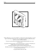
51 Chapter 6: Installation Siting The control head is completely waterproof and should be sited where it is: Within easy reach of the steering position Protected from physical damage At least 230 mm (9 in) from any compass At least 500 mm (20 in) from any radio/radar receiving/transmitting equipment Note: The back cover is designed to breath through the cable boss to prevent moisture accumulation. This must be protected from the weather by following the mounting procedure.
52 ST6000 Plus Autopilot Control Unit Owner,s Handbook 4. Screw the fixing studs (2) into the display head. 5. Pass the cables (SeaTalk, NMEA) through the bulkhead. 6. Fit the cables to the appropriate terminals (see relevant subsection for connection details of each item) 7. Fit the display head to the bulkhead. 8. Assemble the thumb nuts (3) onto the fixing studs (2). 9. Tighten the thumb nuts by hand until the display head is secure.
53 Chapter 6: Installation D3445-1 Typical SeaTalk cabling ST6000 Plus Repeater SeaTalk Instrument 100/300 Course Computer SeaTalk Bus ST6000 Plus Control Head D3446-1 6.3 NMEA interface ST6000 Plus accepts NMEA navigation data for display and use in Track and Vane modes. The required NMEA data formats are shown in the table at the end of this section. Cabling The NMEA port should be connected to a Navigator or Wind instrument.
54 ST6000 Plus Autopilot Control Unit Owner,s Handbook Navigator with NMEA output Red (Data In +ve) Blue (Data In -ve) D3442-1 NMEA cable connectors NMEA connections are made using spade connectors. When fitting the spade connectors, make sure the connector fits securely over the blade and not between the connector and its plastic insulating boot incorrect fitting will give intermittent contact which will lead to faulty autopilot operation.
55 Chapter 6: Installation The following NMEA 0183 wind and navigation data can be decoded by the ST6000 Plus.
56 ST6000 Plus Autopilot Control Unit Owner,s Handbook Switch on Having installed your ST6000 Plus, switch on the main power breaker. If the control head is active and the system operating, the following will occur: The control head beeps and displays the pilot type, ST6000. After the pilot type has been displayed for 2 seconds, the Standby mode screen should be displayed. This shows that the control head is active. If the head does not beep, check the fuse/circuit breaker.
57 Chapter 6: Installation SeaTalk interface If the ST6000 Plus has been linked to other SeaTalk instruments via SeaTalk, the link can be checked as follows: 1. Press standby. 2. Select display illumination level 3 on any other SeaTalk instrument or autopilot control unit. The ST6000 Plus should immediately respond by switching on its display illumination.
58 ST6000 Plus Autopilot Control Unit Owner,s Handbook
Chapter 7: Post Installation Procedures 59 Chapter 7: Post Installation Procedures This chapter applies to systems where the ST6000 Plus has been installed as the only control unit for a Type 100/300 Course Computer. Once you have installed the system, you need to confirm that it is wired correctly and is also set up to suit your type of boat.
60 ST6000 Plus Autopilot Control Unit Owner,s Handbook 1. Press auto. 2. Press the +10 key. The helm should move to produce a turn to starboard. D3393-1 3. If the helm produces a turn to port, reverse the motor connections at the course computer. 4. If the helm overshoots and has to drive back or starts to hunt back and forth, you need to increase the Rudder Damping option in Dealer Setup (see Chapter 5).
Chapter 7: Post Installation Procedures 61 Wind transducer interface If the ST6000 Plus is connected to a wind instrument via its NMEA data port or SeaTalk, then the link between the two instruments should be checked as follows: Press standby and auto together. The ST6000 Plus should display the Vane mode screen, with the locked wind angle and locked heading as shown. Alternatively, if the wind data is not received , the ST6000 Plus will display a NO DATA error message.
62 ST6000 Plus Autopilot Control Unit Owner,s Handbook 7.2 Initial sea trial EMC conformance Always check the installation before going to sea to make sure that it is not affected by radio transmissions, engine starting etc.. In some installations, it may not be possible to prevent the equipment from being affected by external influences. In general this will not damage the equipment but can lead to it resetting, or momentarily may result in faulty operation.
63 Chapter 7: Post Installation Procedures Automatic compass deviation correction The ST6000 Plus will correct the fluxgate compass for most deviating magnetic fields. Compass errors due to deviating magnetic fields can be up to 45°, depending on your vessel type. The correction procedure reduces these to a few degrees, so it is essential to perform the procedure as the first item in your initial sea trial.
64 ST6000 Plus Autopilot Control Unit Owner,s Handbook 4. Press the +1 or -1 key to change the setting from OFF to YES. The Turn Boat page is then displayed. D3451-1 5. Keeping the boat speed below 2 knots, turn the vessel in slow circles. It should take at least 3 minutes to complete 360°. 6. Keep turning your boat until the unit beeps and the Deviation screen is displayed. This shows the maximum deviation detected, and indicates that compass correction has been completed successfully.
Chapter 7: Post Installation Procedures 65 8. Use the +1 and -1 keys, or the +10 and -10 keys, to increase or decrease the displayed heading, until it agrees with the ships steering compass or a known transit bearing. 9. Press and hold standby for 2 seconds to exit calibration and save the new settings. Note: Setup options are always saved on exit. Further heading alignment adjustment You should always check the compass alignment after swinging the compass.
66 ST6000 Plus Autopilot Control Unit Owner,s Handbook Checking autopilot operation Having calibrated the compass the following proceedure is recommended to familiarise yourself with autopilot operation: 1. Steer onto a compass heading and hold the course steady. 2. Press auto to lock onto the current heading. A constant heading should be achieved in calm sea conditions. 3. Use the -1, -10, +1 and +10 keys to alter course to port or starboard in multiples of 1° and 10° 4.
Chapter 7: Post Installation Procedures 67 These actions are most easily recognised in calm sea conditions where wave action does not mask basic steering performance. 2. Refer to Chapter 5, Customising the System, for instructions on how to adjust the default rudder gain setting. Note that you can also make temporary adjustments to rudder gain during normal operation (see section 3.3). 3. Repeat the test until a crisp course change with no more 5° of overshoot is achieved.
68 ST6000 Plus Autopilot Control Unit Owner,s Handbook
Chapter 8: Maitenance 69 Chapter 8: Maintenance General In certain conditions, condensation may appear on the LCD window. This will not harm the unit, and can be cleared by switching on the illumination for a while. Never use chemical or abrasive materials to clean your autopilot. If the pilot is dirty, wipe it with a clean, damp cloth. Periodically check the cabling for chafing or damage to the outer casing replace any damaged cables.
70 ST6000 Plus Autopilot Control Unit Owner,s Handbook
Chapter 9: Fault Finding 71 Chapter 9: Fault Finding All Raytheon products are subjected to a comprehensive test procedure prior to packing and shipping. In the unlikely event that a fault does occur with your autopilot, the following check list should help identify the problem and provide a cure. The autopilot display is blank No power check the fuse/circuit breaker. The autopilot display shows CODE LOCK at power on The CodeLock code must be entered manually (see Chapter 4).
72 ST6000 Plus Autopilot Control Unit Owner,s Handbook The autopilot will not “talk” to other SeaTalk instruments Cabling problem make sure all the cables are connected properly. Position information not received Navigator not transmitting the correct position data. The autopilot will not auto advance to the next waypoint No bearing to waypoint information received from the navigator.
73 Index Index A Adjusting the Locked Wind Angle 20 Advance 18 Advanced Operation 13 Advice 69 Alarms 24 Apparent wind angle Adjusting 20 Previous 21 Auto mode 5 AutoAdapt 45 Automatic Acquisition 14 Automatic Compass Deviation Correction Automatic Deadband 23 Automatic track acquisition 14 AutoRelease 47 AutoSeastate 23 AutoTack 7 To Port 8 To Starboard 7 Vane mode 22 AutoTrim 43 63 B Bar graph 4 Bar Selection 35 Basic Operation 3 C Cabling 50, 69 Calibration Lock 40 Cancelling a Dodge Manoeuvre 18 cha
74 ST6000 Plus Autopilot Control Unit Owner,s Handbook Compass alignment 64 Compass Deviation Correction 35 Compass deviation correction 35, 63 Connections to the SeaTalk Bus 52 Control Head 50 Course changes 5 operating hints 9 Course Changes Under Autopilot Control Cross Track Error 16 Cross track error (XTE) 16 Cruise Speed 42 Cruise speed 47 Customising the autopilot 3348 D Data Not Received 26 Data Pages 11, 36 Setting up 36 Deadband 23 Dealer Setup 38, 3848 Deviation 64 Deviation Display 35 Diseng
75 Index F Fault Finding 71 Fault finding 71 Functional test 5557 course computer installations 59 Functional Test (Repeater Unit) 55 Further Heading Alignment Adjustment G Graph use 35 H Hand steering 5 Heading 6 Heading alignment 35 Heading alignment adjustment Heading mode 35 65 I Illumination 10 Initial calibration 59 Initiating a Dodge Manoeuvre Initiating Track Mode 13 Installation 49 Interfaces 56, 60 Intermediate Setup 29 18 K Key functions 3 Keypad Illumination 10 L Large Cross Track Erro
76 ST6000 Plus Autopilot Control Unit Owner,s Handbook M Maintenance 69 Major Course Changes 9 Man Overboard (MOB) 27 Manual Acquisition 15 Manual mode 10 Manual steering 5 Manual track acquisition 15 Master unit (CodeLock) 29 Minimum Deadband 23 N Navigation data displays 11 Navigation Interface 56, 60 Navigation interface (GPS, Decca, Loran) NEXT WPT 26 NMEA Cable Connectors 54 NMEA Data Transmission 54 NMEA Interface 53 No Data alarm 26 No Link 25 56, 60 O Off Course 25 Off Course Alarm 8, 42 Off Cou
77 Index R Recommended Settings 39 Recording Calibration Settings 47 Response 41 Response level 23 Default setting 41 Returning to the Previous Locked Heading Rudder bar 35 Rudder Calibration 36 Rudder damping 46 Rudder Gain 40 Rudder gain 24, 40, 66 Rudder Limit 41 Rudder offset 41 S Safety 18 Sea trial 62 SeaTalk data displays 11 SeaTalk Failure 25 SeaTalk interface 57, 61 Servicing 69 Servicing and Safety 69 Setting Waypoints 19 Skipping a Waypoint 18 Specification 2 Standby mode 5 Steering bar 35 Swing
78 V Vane Mode 20 Vane mode 1920 Variation 45 Verifying Computed Positions 19 Version number 31 W Watch alarm 27 Waypoint Advance 26 Waypoint arrival and advance 17 Wind Shift alarm 22 Wind transducer interface 61 Wind Trim 47 WindTrim 19, 1920 ST6000 Plus Autopilot Control Unit Owner,s Handbook
Drill 5mm (3/16in) Drill 5mm (3/16in) Machine hole 90mm (3.
Limited Warranty Certificate Raytheon Marine Company warrants each new Light Marine/Dealer Distributor Product to be of good materials and workmanship, and will repair or exchange any parts proven to be defective in material and workmanship under normal use for a period of 2 years/24 months from date of sale to end user, except as provided below. Defects will be corrected by Raytheon Marine Company or an authorized Raytheon dealer.
United States of America Raytheon Marine Company Recreational Products 676 Island Pond Road Manchester, NH 03109-5420 U.S.A.