
Installation Manual Part 1

FCC ID: CDG-ARTU
MAGNASTAR
EXHIBITC
C-2000 DIGITAL AIRBORNE TELEPHONE SYSTEM
f)
Measure cable RF loss at 900 MHz if test equipment is available.
Note: The total RF cable path loss from the ARTU to the ANTENNA should not exceed 3 dB. The two
different RF paths include the combination of the Antenna and Receive cables or the Antenna and
Transmit cables. The lengths of the RF cables are limited by this requirement.
Aircraft Power Cable
Prior to installation of the ARTU. verify the power cable installation for proper interconnection and correct
voltages. Calculate the voltage drop based on wire gauge and rated system current. Required check list
for this cable is:
POWER CABLE CHECK LIST
a) Visually inspect cable for bent or damaged pins.
b) Continuity check for proper pin-to-pin interconnection between cable connectors.
c) Check for open circuit condition between each pin and the back shell.
d) Check for open circuit condition between each pin and all other connector pins.
e) Apply aircraft power to the Power Cable. Check for correct voltage on the proper pins.
f) Check for ground connection on the proper pins.
g) Check for the absence of ground or aircraft power on all other connector pins.
RJ-11 Cables
Prior to installation of a FAX or Modem to a Handset. check the RJ-11 cable for proper interconnection. A
required check list for this cable is:
a) Visually inspect cable for bent or damaged pins.
b) Continuity check for proper pin-to-pin interconnection between cable connectors.
c) Check for open circuit condition between each pin and all other connector pins.
MagnaStar Maintenance Terminal (MMT Cable)
Note: Do not permanently connect the MMT cable to the ARTU. This connector port is for
checkout and troubleshooting only. For normal operation, disconnect the MMT cable and replace
the dust cover on the ARTU MMT connector.
With the MMT cable connected. after power up. the ARTU will not start running its operational software
until instructed to do so by the MMT unit.
4.3
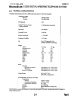
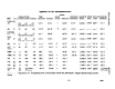
Connector Kit Drawings
The connector kit drawings provide detailed instructions for constructing the interface cabling using the
parts provided with an individual unit in the connector kit. The connector kit drawings are shipped with
each unit and are provided in the installation manual for reference. The connector kit drawings included
in the installation manual are as follows:
744434 - TMU Connector Kit. use:
ARTU Connector Kit Drawing - 744319
743425 - AIU Connector Kit Drawing
744319 - ARTU Connector Kit Drawing
744321 - CDBR-1 Connector Kit Drawing
744428 - CDBR-2 Connector Kit Drawing
4-2
ReYB