
User's Manual

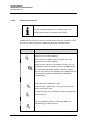


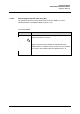


Table Of Contents
- 0 General
- 1 BASIS SETTINGS TO USE THIS RADAR
- 2 OPERATING INSTRUCTION
- 2.1 Radar Operation
- 2.2 Set to Operation
- 2.3 Display Organization and Submenu Structure
- 2.3.1 Sensitivity Controls
- 2.3.1.1 Gain and Clutter Processing
- 2.3.1.2 Tune
- 2.3.1.3 Gain
- 2.3.1.4 Sea
- 2.3.1.5 Rain Rate
- 2.3.1.6 Automatic Clutter Reduction
- 2.3.1.7 Filtering Rain Clouds FTC
- 2.3.1.8 Search and Rescue Transponder SART ON/OFF
- 2.3.1.9 Pulse Width Selection (only available in Master mode)
- 2.3.1.10 Interference Selection IR ON/OFF
- 2.3.1.11 Echo Expansion EXP. ON/OFF
- 2.3.2 Radar Video Displays
- 2.3.3 Radar Video Settings
- 2.3.4 Navigational Elements MAP, PIL, EBL and VRM
- 2.3.5 Cursor Information
- 2.3.6 Cursor in Park Position
- 2.3.7 Information Panel
- 2.3.1 Sensitivity Controls
- 2.4 Select Target Information TGT INFO
- 2.5 Target Menu
- 2.6 Zone Management
- 2.7 Function Menu
- 2.7.1 Select the Backlight Menu Brightness Control and Color Palette
- 2.7.2 Select T-SCE (ON/OFF)
- 2.7.3 Select Route (Option)
- 2.7.4 Select Zoom Menu
- 2.7.5 Select Sector Blanking (ON/OFF)
- 2.7.6 System Clear
- 2.7.7 Performance Monitor (PMU)
- 2.7.8 Magnetron Current
- 2.7.9 Test Alert
- 2.7.10 Senc Menu
- 2.7.11 Chart Info
- 2.8 Chart Radar Function
- 2.9 Select ARPA Trial Manoeuvre
- 2.10 Sea Scout (Option)
- 2.11 Alarm and Warning messages and handling
- 2.12 Working Around the Radar Antenna
- 3 Theory of Operation
- 4 Index

Synapsis Radar
with Nautoscan NX Pedestal
Operator Manual
4265.DOC020102
2-92
Edition July 2015
2.3.4.2 Parallel Index Line PIL
The PIL function depends on the heading signal. No
heading signal means no results in PIL function.
Parallel index lines PIL are used to mark the limits of areas or channels. These
lines can be used to observe the advancing along an intended course.
Operator controls
Task
Step 1 Select the PIL MENU soft button the menu
appears in the functions display.
Step 2 Select the SWITCH PIL soft button the menu
appears in the functions display.
Within the PIL selection it is possible to create up to 10
parallel index lines on the PPI. The PILs are labeled with
the corresponding number. Before creating a parallel
index line the operator can determine the stabilization type
via soft button (NORTH STABILIZED or OWNSHIP
STABILIZED).
Step 3 Select the stabilization type.
Step 4 Create a parallel index line by pressing PI1 soft
button (see Figure 2-32).
The PIL bearing can be switched to relative bearing value
or true bearing.
The current distance (DST) and bearing (BRG) are
adjustable by the slider function.