Service Manual RaySafe i2 Installation and maintenance
© 2013.01 Unfors RaySafe 5001050-C All rights are reserved. Reproduction or transmission in whole or in part, in any form or by any means, electronic, mechanical or otherwise, is prohibited without the prior written consent of the copyright owner.
RaySafe i2 Installation and maintenance manual – Contents Contents Introduction......................................................................................................4 About the RaySafe i2 System...........................................................................4 How the system works.................................................................................... 5 About this user manual....................................................................................
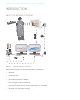
RaySafe i2 Installation and maintenance manual – Introduction Introduction About the RaySafe i2 System Figure 1.
RaySafe i2 Installation and maintenance manual – Introduction How the system works The dosimeter measures and records X-ray exposure every second and transfers the data wirelessly, via radio, to the real time display. The real time display shows real time dose exposure from up to eight dosimeters in range. Color indication bars (green, yellow, red) represents the intensity of the currently received exposure. The accumulated dose per individual is displayed next to the color indication bars.
RaySafe i2 Installation and maintenance manual – Installation Installation Package contents Note: The content is dependent of purchased configuration.
RaySafe i2 Installation and maintenance manual – Installation Real time display installation WARNING: Switch off the system before starting any installation or replacement activities. NOTE: The real time display is delivered with the required software installed. NOTE: In multiple real time display setups, the individual real time displays should be placed in separate rooms. Note: The user’s software version may differ from the one on the screenshots in the manual, without any change in functionality.
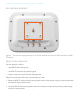
RaySafe i2 Installation and maintenance manual – Installation Real time display Interfaces 4 1 2 3 Figure 2. The real time display interfaces: 1: 12 V DC, 2: ethernet connection, 3: USB connection, 4: VESA 75 interface Mount the real time display The wall support kit contains: • one VESA 75 wall mounting plate • one VESA 75 real time display mounting plate • fixation screws and plugs for the wall mounting plates Follow the steps below to mount the real time display on a wall: 1.
RaySafe i2 Installation and maintenance manual – Installation 3. Drill the holes as marked, using the masonry or wood drill as appropriate. 4. Mount the VESA 75 wall mounting plate to the wall using the provided screws and plugs. 5. Position the real time display with its mounting plate on the wall mounting plate. Power Supply A 12V power adaptor (Astec DPS53-M, FW7556M/12) powers the real time display.
RaySafe i2 Installation and maintenance manual – Installation User Settings Menu Figure 3. The user settings menu consists of one screen. Adjust the backlight level of the screen by moving the bar horizontally. This change will take effect immediately.
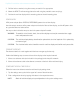
RaySafe i2 Installation and maintenance manual – Installation Admin Settings Menu The admin settings menu consists of four screens. Access these screens by tapping the arrow buttons in the lower right corner of each screen. Real time display name and location menu Figure 4. The real time display name and location menu. Enter appropriate name and location of the real time display. This information is used to identify the real time display so that it can be found in dose manager.
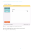
RaySafe i2 Installation and maintenance manual – Installation Reserved slots menu Figure 6. The reserved slots menu. This is an optional setting, which you can use to reserve a number of slots in the online view for the clinical roles doctor, nurse and technician. If you, for example, have reserved three slots for doctors but the real time display detects only one, there will be two empty slots before the first nurse appears.
RaySafe i2 Installation and maintenance manual – Installation Network setup menu Figure 7. The network setup menu. Configure the network connection between the real time display and the dose manager. You might have to contact the local IT department to receive the IP address. If you change this information, the real time display requires a restart. NOTE: Network setup is only applicable if you are using the dose manager software.
RaySafe i2 Installation and maintenance manual – Installation Time and date menu Figure 8. The time and date menu. Set time, date, time zone and manage daylight saving time for the real time display. For daylight saving time, you can select to manage it manually or by selecting a daylight settings region for your time zone. The possible regions available for daylight saving time are different depending on your current time zone.
RaySafe i2 Installation and maintenance manual – Installation System settings menu The system settings menu consists of three screens. Access these screens by tapping the arrow buttons in the lower right corner of each screen. Touch screen menu and dose Figure 9. The touch screen and dose menu. If the touch screen is disabled in the online view; enable it by checking the touch screen check box. NOTE: The settings button and menu is always active.
RaySafe i2 Installation and maintenance manual – Installation Check the box Show accumulated procedure dose to show a column with the accumulated dose since last tap on the reset button in the lower right corner of the online view. The accumulated dose per examination will also be reset when restarting the real time display. Note The accumulated dose per examination is only recorded in the real time display memory. The values recorded in the dosimeter is not affected.
RaySafe i2 Installation and maintenance manual – Installation NOTE: To prevent dosimeters not currently in use to show up on a real time display, the dosimeter rack should be located preferably more than 10 meters away from the real time display and not in line of sight. Language menu Figure 11. The language menu. Follow the instructions below to change the language in the real time display: 1. Choose your preferred language. The change will take effect after a restart, see steps 2–3 below 2.
RaySafe i2 Installation and maintenance manual – Installation • One USB port available • 1 GB of system memory available • 40 GB hard drive with at least 15 GB of memory available • Recommended screen resolution at least 1024 x 768 Installation Follow the instructions below to install the dose viewer application and the cradle driver: NOTE: Do not connect the cradle to the computer until dose viewer is properly installed. 1.
RaySafe i2 Installation and maintenance manual – Installation Dose manager installation System Requirements • Operating systems: Windows 7, Windows Vista or Windows XP • .NET 3.5 • One USB port available • 2 GB of system memory available • 40 GB hard drive with at least 15 GB of memory available • Recommended screen resolution at least 1280 x 1024 Installation Dose manager and real time display are connected using the local hospital network.
RaySafe i2 Installation and maintenance manual – Installation • the system requirements are met. • you are logged on as local administrator. • there is no previous version of dose manager installed on the computer (see “Dose manager software update” on page 28). If Windows does not automatically install the cradle driver when the cradle is first connected to a PC, you need to install it manually. All the driver files are located on the installation CD in the folder “CradleDriver”.
RaySafe i2 Installation and maintenance manual – Installation Configure the dosimeter in dose manager or dose viewer Figure 13. The dosimeter options dialog box Follow the steps below to configure a dosimeter: 1. Put the dosimeter in the cradle. Within a few seconds dose viewer/manager will have detected the dosimeter. 2. Dose view/manager will start loading the dosimeter dose history. Follow the progress in the progress bar in the lower left corner. 3. Open the dosimeter options dialog box.
RaySafe i2 Installation and maintenance manual – Installation • Press the Information tab and select Displayed symbol corresponding to the dosimeter’s real color. • Press the Save button. 4. Wait for a couple of seconds before you remove the dosimeter from the cradle after you have saved the changes. WARNING: Always power OFF the dosimeters before transport.
RaySafe i2 Installation and maintenance manual – System function tests System function tests We recommend these tests in order to verify the correct installation and configuration of the RaySafe i2 system. Expose dosimeter to radiation Follow these steps to expose a dosimeter to scattered radiation in the other tests described below: 1. Place the dosimeter outside the primary beam, close to a phantom placed in the X-ray beam, so that the dosimeter receives scattered radiation.
RaySafe i2 Installation and maintenance manual – System function tests Figure 14. Dosimeter data in dose viewer Real time display test Online View Test Follow the instructions below to verify that the dosimeter appears in the real time display: 1. Check that the dosimeter appears in the real time display’s online view within 30 seconds. 2. Expose the dosimeter to radiation (see “Expose dosimeter to radiation” on page 23). The real time display will show the dose instantaneously (see figure below).
RaySafe i2 Installation and maintenance manual – System function tests Figure 15. The real time display Online View Communication Range Test Check that the dosimeter communication range configuration is correctly tuned, that is, dosimeters stored away from the real time displays shall not appear on the real time displays online view, but will appear when they approach the display. See section “Dosimeter communication range menu” on page 16.
RaySafe i2 Installation and maintenance manual – Measurement performance verification Measurement performance verification The purpose of this test is to verify the measurement performance of dosimeters using scattered radiation from diagnostic X-ray units. Unfors RaySafe recommends the following arrangement: CAUTION: Do not expose yourself to X-ray radiation.
RaySafe i2 Installation and maintenance manual – Software Update and maintenance Software Update and maintenance A software update package consists of a new version of the application in question. Real time display software update Follow the instructions below to update the real time display software: 1. Save the entire folder ‘swupdate’ from the update package to a USB memory. 2. Press and hold on the welcome screen that appears during real time display startup for 10 seconds to enter the Setup view. 3.
RaySafe i2 Installation and maintenance manual – Software Update and maintenance Troubleshooting If the update procedure fails, remove any previous versions of the dose viewer application and re-install the software update package. NOTE: Removing a previous version of the dose viewer application will cause the dose history and the passwords settings of that version to be deleted.
RaySafe i2 Installation and maintenance manual – Technical Data Technical Data Real time display Characteristic Measure Weight 1.2 kg Dimensions 297x243x51 mm (WxHxD) Display 10.4” touch screen, 640x480 pixels, 65 000 colors Power supply 12 V, 2 A (Astec DPS53-M, FW7556M/12) Memory 512 MB Storage 290 hours of dose history for each of 50 dosimeters Backlight life time Approximately 50000 hours Maximum heat dissipation 25 W Network Ethernet 10/100 Mbps USB 1.
RaySafe i2 Installation and maintenance manual – Technical Data Characteristic Measure Radio frequency 868.3 MHz, 918.3 MHz, 927.9 MHz (depending on purchased configuration) The product label is located at the back of the dosimeter. Cradle Characteristic Measure Weight 50 g Dimensions 64x61x59 mm (WxHxD) Cable length 1,5 m Power via USB Communication with computer USB 2.0 The product label is located at the bottom of the cradle.
RaySafe i2 Installation and maintenance manual – Technical Data Climatic conditions Classes: C1 Indoors, temperature controlled Parameter Measure Temperature levels: – for performance +15°C to +35°C – for safety +10°C to +40°C – for storage -25°C to +70°C Temperature rate of change < 0.
RaySafe i2 Installation and maintenance manual – Installation settings form Installation settings form Fill in the settings in the following tables when installing the real time display and return this form to Unfors RaySafe.
RaySafe i2 Installation and maintenance manual – Installation settings form Time zone: Daylight saving time: Show Accumulated Procedure Dose (enabled or disabled): Show units in rem instead of Sv (enabled or disabled): Dosimeter communication range: 33