CATALOG NO. 6000.52-AG Effective: 09-01-03 Replaces: 06-15-03 INSTALLATION AND OPERATING INSTRUCTIONS Models P-R185A to P-R405A C-R185A to P-R405A Low NOx P-R185AL to P-R405AL C-R185AL to C-R405AL RP2100 SWIMMING POOL and SPA HEATER WARNING: If the information in these instructions are not followed exactly, a fire or explosion may result causing property damage, personal injury or death. — Do not store or use gasoline or other flammable vapors and liquids in the vicinity of this or any other appliance.
CONTENTS 3 PART ONE OWNER'S OPERATING INSTRUCTIONS 3 SECTION 1 START-UP PROCEDURES 3 4 Before Start-Up Lighting Instructions & Shut-Off Procedure (Manually Lighted Pilot MV) Operating Instruction & Shut-Off Procedures (Automatically Lighted Pilot IID) After Start-Up 5 6 6 SECTION 2 CAUTION 6 SECTION 3 MAINTENANCE & CARE PROCEDURE 7 7 8 Pool & Spa Water Chemistry Cold Weather Operation Winterizing the Pool & Spa Heater 8 PART TWO INSTALLATION/SERVICE INSTRUCTIONS 8 SECTION 1 RECEIVING EQUIPMEN
PART ONE - OWNER'S OPERATING INSTRUCTIONS FOR YOUR SAFETY - READ BEFORE OPERATING WARNING: IF YOU DO NOT FOLLOW THESE INSTRUCTIONS EXACTLY, A FIRE OR EXPLOSION MAY RESULT, CAUSING PROPERTY DAMAGE, PERSONAL INJURY OR LOSS OF LIFE. SECTION 1 / START-UP PROCEDURES Your Raypak Pool/Spa heater has been designed for years of safe and reliable pool/spa water heating. It is available in millivolt or electronic control options. ASME certified units, typical used in commercial applications, are also available.
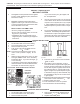
CAUTION: Propane gas is heavier than air and will settle on the ground. Since propane can accumulate in confined areas, extra care should be exercised when lighting propane heaters. LIGHTING INSTRUCTIONS AND SHUT-OFF PROCEDURES MANUALLY LIGHTED PILOTS MILLIVOLT SYSTEM A. This appliance has a pilot that must be lighted by hand. When lighting the pilot, follow these instructions exactly. B. BEFORE LIGHTING smell all around the appliance area for gas.
CAUTION: Propane gas is heavier than air and will settle on the ground. Since propane can accumulate in confined areas, extra care should be exercised when lighting propane heaters. OPERATING INSTRUCTIONS AND SHUT-OFF PROCEDURES AUTOMATICALLY LIGHTED PILOTS ELECTRONIC IGNITIONS SYSTEMS A. This appliance is equipped with an ignition device which automatically lights the pilot. Do not try to light the pilot by hand. *If you cannot reach your gas supplier, call the fire department. B.
SECTION 2/CAUTION AFTER START-UP Feel the inlet and outlet pipes. Outlet pipe should be only slightly warmer than the inlet. It should not be hot. Elevated water temperature can be hazardous, and the U. S. Consumer Product Safety Commission recommends the following guidelines: WARNING: Should overheating occur or the gas supply fail to shut off, turn off the manual gas control to the appliance. 1. Spa or hot tub water temperatures should never exceed 104°F (40°C).
4. Make visual check of the burner and pilot flame. Flame pattern on the main burner and pilot is indicated in the previous illustration. Yellow flame means restriction of the air openings. Lifting or blowing flame indicates high gas pressure. Low flame means low gas pressure. Should this occur, shut the heater off and contact your gas supplier or qualified service agency.
WINTERIZING THE POOL & SPA HEATER Return Header When heaters installed outdoors in freezing climate areas are to be shut down for the winter, observe the following step-by-step procedure: 1. Turn off gas valve, manual gas valve, and electrical supply to the heater. 2. Open drain plug located on the inlet/outlet Drain Plug header, (under water pipes). Remove the heat Fig.
SECTION 3 / INSTALLATION INSTRUCTIONS CALIFORNIA PROPOSITION 65 WARNING: This product contains chemicals known to the State of California to cause cancer, birth defects or other reproductive harm. IMPORTANT NOTICE CLEARANCES ALL HEATERS For clearances from combustible surfaces, see the chart below. These instructions are intended for the use of qualified personnel only, specifically trained and experienced in the installation of this type of heating equipment and related system components.
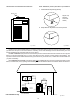
HEATER WITH OUTDOOR STACKLESS TOP VENT TERMINAL (Outdoor) Stackless Top Installation 1. Insert tabs into keyhole (4 places). Outdoor Top Pagoda Top (Shipped Loose with Heater) 2. Snap tabs into keyholes so as not to pull out. Fig. # 8278.1 Fig. #RP8280.1 Heaters must not be installed under an overhang of less than three (3) feet from the top of the heater. Three (3) sides must be open in the area under the overhang.
INDOOR HEATER The design is also certified for indoor installation when equipped with the approved draft hood. For Canada, indoor installation is restricted to an enclosure that is not occupied and does not directly communicate with occupied area. Refer to the latest edition of CAN/CGA-B149.1 and B149.2 for specific requirements. Locate heater as close as practical to a chimney or gas vent. Heater must always be vented to the outside. See Vent Piping Section for venting details.
Securing the top panel cover- INDOOR KIT ONLY 7. Re-install the louvered top. 8. Mount the draft hood onto the adapter plate lip inside the heater. See Fig. 6. 9. Proceed to installing the clips, step 14. Securing the top panel cover- OUTDOOR KIT ONLY 10. After removing the drafthood from the box, slide the top panel cover over the draft hood. See Fig. 1. 11. Holding both pieces together, mount the draft hood on the adapterr plate lip inside the heater. See Fig. 6. 12.
Installing the top cover- OUTDOOR KIT ONLY 22. Remove the two pieces ofg metal tape holding the top panel cover up and discard. 23. Insert the rear two tabs into the slots on the heater top and slide the top panel cover backwards. See Fig. 13. 24. Lower the top panel cover and using your thumbs, push tabs in and insert the two front tabs into the slots on the top of the heater. See Fig. 14. 25. Lower the top panel cover flush to the top and release the tabs. They will spring into place as shown in Fig. 15.
SPECIFICATIONS AND DIMENSIONS *Designation for Propane is "EP", Natural gas is "EN". Prefix "C" is for Cast Iron (ASME) Headers; "P" is for Plastic (Capron) Headers. Reduce input 4% for each 1000 ft. above sea level when installed above 2000 ft. elevation. For Canada, no derate is required for elevations up to 4500 feet. Manufactured under Patent No. 3,623,458. Note: Plastic (Capron) Headers cannot be used for ASME installations. Fig # 9037.1 *Electrical Connection On Left Side is 19-1/8".
VENT PIPING WARNING: Indoor boilers require a drafthood that must be connected to a vent pipe and properly vented to the outside. Failure to follow this procedure can cause fire or fatal carbon monoxide poisoning. Vent piping the same size as the draft hood outlet is recommended, however, when the total vent height is at least ten (10) feet (draft hood relief opening to vent terminal), the vent pipe size may be reduced as specified in Chapter 10 of the National Fuel Gas Code, ANSI Z 223.1.
NOTE: Do not use teflon tape on gas line pipe thread. A flexible sealant is recommended. ELECTRONIC IGNITION GAS VALVES-CONTINUED A minimum of 7" W.C. and a maximum of 14" W.C. upstream pressure under load, and no load conditions must be provided for natural gas or a minimum of 12" W.C. and a maximum of 14" for propane gas. GAS PRESSURE REGULATOR Fig # 9328 The gas pressure regulator is preset at 4" W. C. for natural gas, and 11" W. C. for propane gas.
Plumbing from the heater back to the pool must not have any valves or restriction that could prevent flow when the pump is operating. CAUTION: An additional source of heated water, i.e. a solar system, must be connected to the main line ahead of the heater inlet pipe in order for it to act as the primary heat source. If the primary system provides adequate heat to maintain setpoint, the RP2100 heater will not fire.
UNITHERM GOVERNOR OPERATION AUXILIARY BYPASS VALVE ADJUSTMENT CAUTION: The patented Unitherm Governor is a thermostatic mixing valve specifically designed to maintain constant heater internal temperature between 105° to 115°F despite continually changing flow rates from the filter and changing pool temperatures. This narrow range is needed to prevent damaging condensation on the burners which will occur if the heater runs for any length of time below 100°F.
RP2100+ Heat Exchanger Reversal Procedure (Capron Resin Header Models) 1. Remove right and left side access panels (Figure 1). 2. Disconnect wires at high limit, AGS (automatic gas shutoff), and pressure switch on the inlet/outlet header (Figure 2). 3. Electronic Ignition Heaters: Remove the thermostat temperature sensor by loosening the compressionfitting nut (Figure 3). Reroute the sensor to the left side of the heater. 4.
JACO FITTING Fig. #3 NOTE: Tighten almost flushed (1/32" to 1/8") to the header to avoid leaks. BULB & CLIP Fig. #4 RE-INSTALLED IN/OUT HEADER ON OPPOSITE SIDE. Fig.
Option Location For Left Side Field Wiring ELECTRICAL WIRING Control Box (Factory Mounted Location) NOTE: If it is necessary to replace any of the original wiring, it must be replaced with 105° C wire or its equivalent, and /or 150° C wire or its equivalent as originally built. MILLIVOLT SYSTEM The Millivolt System residential heater is equipped with a self-generating electrical system in which the electric current is provided by means of a pilot generator.
For 120 V input power to the unit, connect the black wire to the “L1” or hot leg of the power supply. Connect the white wire to the “L2” or neutral leg of the power supply. Attach the wire nut to the red wire. There should be no connection to the red wire for 120V operation. For Low NOx pool heaters wire nut each red wire independently. WIRING DIAGRAM KEY PINK CONNECTOR BLUE CONNECTOR Fig. # RP8096 WIRING DIAGRAM MILLIVOLT UNITS WITH MECHANICAL THERMOSTAT Fig.
WIRING DIAGRAM - IID UNITS (atmospheric) 23
WIRING DIAGRAM - IID UNITS (Low NOx) 24
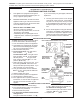
SECTION 4 / SERVICING INSTRUCTIONS GENERAL LOCATION OF CONTROLS Drain Plug (Located in Return Header) CONTROLS/ADJUSTMENTS/REPLACEMENTS Bypass Temperature Adjust Buttons Hi Limit (Located in Return Header) Mode Button LCD Display AGS HiLimit (Located in Inlet/ Oulet Header) Ignition Control (IID) Digital Thermostat Module Unitherm Governor Roll-Out Switch Fig. #2000 Drain Plug Gas Valve Pilot On-Off Switch Transformer Fig #2005 CONTROL PANEL REMOVAL 1.
ELECTRONIC CONTROLS Notice to owner- Thermostat operation Your heater is equipped with a microprocessorcontrolled thermostat that controls the pool or spa temperature by measuring the etmperature of water coming back through the heater. It will then monitor the temperature and turn the heater back on when it senses that the temperature is falling below set point. Small fluctuations in the return temperature are experienced during the operation of the heater.
TEMPERATURE DISPLAY-Fahrenheit vs. Centigrade The RP2100 digital heaters will display metric (Centigrade) units. The factory default setting is Farenheit. If you open up the front panel so you are looking at the front of the digital board, you will find two small round buttons, labled S1 and S2. S1 is labeled "C of F". Hold down the S1 button for several seconds, until the board displays "CCC", this will set the board to display in Centigrade.
Note: ElectroStatic Discharge (ESD) damage can be caused by direct or indirect contact with the wiring or circuit board. When one walks to the heater area, an electrostatic charge accumulates on the body. Contact of a finger allows the body to discharge, possibly causing device damage.
PRESSURE SWITCH The pressure switch, or heater actuator, insures that the heater operates only when the filter pump is in operation. It is located on the inlet/outlet header. It is factory set at 1.75 PSI for deck level installations. When the heater is located below the level of the spa or pool, it may be necessary to reset the pressure switch to compensate for the no-flow static head.
BURNER DRAWER REMOVAL 1. Shut off main electrical power switch to heater. 2. Shut off gas upstream of heater. 3. Remove front door. 4. Disconnect gas line from gas valve. 5. Remove (2) screws that mount burner tray to unit, and (2) screws that secure gas valve to jacket. 6. Disconnect wires that terminate at gas valve. 7. Slide out burner tray. 8. Reverse above procedure to reinstall. GAS VALVE REMOVAL 1. Shut off gas supply to the heater. Remove gas piping to gas valve inlet. 2.
Extension Pieces (2) Auger with Carbide Tip TUBE CLEANING PROCEDURE Establish a regular inspection schedule, frequency depending on local water condition and severity of service. Do not let the tubes clog up solidly. Clean out deposits over 1/16" in thickness. The heater may be cleaned from the return header side, without breaking pipe connections. It is preferable, however, to remove both headers for better visibility through the tubes and to be sure the ground-up lime dust does not get into the system.
ADDENDA: LOW NOx POOL HEATERS The Raypak Low Nox Pool Heaters are certified and tested under the ANSI Z21.56.CSA 4.7 Standards for gas fired pool heaters. BURNER ADJUSTMENT This burner assembly does not require any primary air adjustments. The heater should be installed to meet all local codes, the latest editions of the National Fuel Gas Code Z223.1 and the National Electrical Code, ANSI/NFPA 70. VISUAL INSPECTION Flame can be observed through the slot opening above the plenum.
ADDENDA: LOW NOX HEATERS (CONTINUED) 6. Use a long 9/16” socket wrench to remove orifices from the gas manifold. 7. Reverse above procedure to re-install. Fig # 9363 IID PILOT Fig # 9362 PILOT REMOVAL LOW NOx BURNER TRAY ASSEMBLY BURNER DRAWER REMOVAL 1. 2. 3. 4. 5. Shut off main electrical power switch to heater. Shut off gas upstream of heater. Remove front door. Disconnect gas line from gas valve.
SECTION 5 / TROUBLE SHOOTING GUIDE MECHANICAL (FOR QUALIFIED SERVICE PERSONNEL ONLY) IMPORTANT NOTICE These instructions are primarily intended for the use of qualified personnel specifically trained and experienced in the installation of this type of heating equipment and related system components. Installation and service personnel may be required by some states to be licensed. Persons not qualified shall not attempt to install this equipment nor attempt repairs according to these instructions.
ELECTRICAL ( STANDING PILOT MILLIVOLT) RAYPAK POOL OR SPA HEATER ELECTRICAL CHECK WITH MV GAS VALVE CAUTION: For qualified service personnel only. 1. Filter must be on with adequate water flow through heater. 2. Gas valve must be "ON" position. Thermostat set higher than pool water temperature. 3. Jumpers are for temporary check only. If left in place, they could cause the heater to burn up.
WARNING HIGH VOLTAGE For qualified Technicians ONLY ELECTRICAL (ELECTRONIC IGNITION IID) NOTE: Some heaters may be equipped with an ignition module that shuts off pilot gas if pilot fails to light. To reset, interrupt power to heater. Intermittent Pilot System TROUBLESHOOTING HONEYWELL S8600 START TURN GAS SUPPLY OFF.
SECTION 6/REPLACEMENT PARTS LIST NOTE: To supply the correct part it is important that you state the model number, serial number and type of gas when applicable. If determined defective by the Company and within warranty, the part will be returned in kind or equal substitution, freight collect. Credit will not be issued.
9-S 6-S 4-J 2-R 1-R 1-J 12-P 7-S 2-J Fig# 240739 39
Low NOx BURNER TRAY PILOT ASSEMBLIES 3-P 3-P 7-P 3-P 14-P 16-P 16-P 17-P Honeywell IID Atmospheric units Fig. #8124 for units produced prior to 06/01/2000 Honeywell IID Low NOx and Atmospheric units for units produced after to 06/01/2000 Use KIT Number 008155F for Low NOx units Use KIT Number 002003F for Atmospheric units 1-P 9-P 15-P 13-P 5-P 16-P Honeywell MV Fig. #8107 40 Fig.
LIMITED WARRANTY RAYPAK RESIDENTIAL SWIMMING POOL AND SPA HEATERS GAS MODELS 185, 265, 335 & 405 MILLIVOLT 185, 265, 335 & 405 ELECTRONIC GENERAL Raypak, Inc. warrants that the cabinet, burner tray (minus controls) and refractory will be free from defects in materials and workmanship under normal use and service for a period of FIVE YEARS FROM THE DATE OF ORIGINAL PURCHASE FOR A SINGLE FAMILY RESIDENCE (ONE YEAR IF OTHER THAN FOR SINGLE FAMILY RESIDENCE USE).
www.raypak.com Raypak, Inc., 2151 Eastman Avenue, Oxnard, CA 93030 (805) 278-5300 FAX (800) 872-9725 Raypak Canada LTD, 2805 Slough Street, Mississauga, Ontario, Canada L4T 1G2 (905) 677-7999 FAX (905) 677-8036 Litho in U.S.A.