RAYPAK VERMONT RFSDV34 FREESTANDING GAS LOG FIRE Installation and Operating Instructions For Models RFSDV34RFNAU (Natural Gas) & RFSDV34RFPAU (Propane) Page 1 of 27
CONTENTS Part 1: For Your Safety Part 2: Installation Instructions • • • • • • • • Part 3: General Venting Information • • • • Part 4: Part 6: Termination Clearances General Information for Assembling Vent Pipes Vertical Through Roof Applications Install Vertical Venting Operating Instructions • • • • • • • • • Part 5: Start Up Recommendations Locating The Fireplace Clearance to Combustibles Fireplace Dimensions Gas Specifications Gas Inlet and Manifold Pressures Preparation Gas Line Installation
Part 7: Conversion • Gas Type Conversion Instruction Part 8: Wiring Diagram • Wiring Diagram Part 9: Page 3 of 27 Warranty
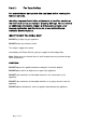
Part 1: For Your Safety For your safety do not operate this appliance before reading this instruction book. Warning: Improper installation, adjustment, alteration, service or maintenance can cause injury or property damage. For assistance or additional information consult with Raypak Australia, your Raypak distributor, qualified installer or accredited Rheem Australia Service Agency. WHAT TO DO IF YOU SMELL GAS? DO NOT try to light any gas appliance. DO NOT touch any electrical switch.
Part 2: Installation Instructions This gas fireplace must be installed by a qualified installer in accordance with AS5601 and all relevant local building codes. For safe installation and operation please note the following: 1. This fireplace gives off high temperatures and should be located out of high traffic areas and away from furniture and draperies. 2.
IMPORTANT: PLEASE READ THE FOLLOWING CAREFULLY Remove any plastic from trim parts before turning the appliance on. It is normal for fireplaces fabricated of steel to give off some expansion and/or contraction noises during the start up or cool down cycle. It is not unusual for the Raypak Vermont gas fireplace to produce some odour the first time it is burned. This is due to residual oils used during the manufacturing process. Please open all windows to ensure your room is well ventilated.
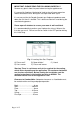
DIMENSION A B C D E F G H I J K Page 7 of 27 RFSDV34 667mm 800mm 492mm 762mm 254mm 394mm 114mm 667mm 333mm 495mm 162mm
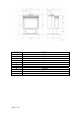
Gas Specifications Model Gas Type Gas Control RFSDV34RFN RFSDV34RFP Natural Propane Radio Freq. Radio Freq. Min. MJ/h Input 22 24 Max. MJ/h Input 32 32 Gas Inlet and Burner Pressures Inlet Minimum Inlet Maximum Burner Pressure Natural Gas 1.1 kPa 3.50 kPa 0.87 kPa ULPG 2.75 kPa 3.50 kPa 2.
Note: When making the gas connection to the appliance inlet fitting, hold the 10mm 3/8” BSP fitting with a spanner when tightening the gas inlet pipe compression nut. For Propane installations an approved gas regulator must be fitted in accordance with AS5601. Ensure copper tube meets the requirements of Australian Standard AS1432 Type B. Note: Heater must be tested for correct operation by the installer after installation is complete.
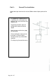
Part 3: General Flue Installation Underside of gas cowl must be at least 500mm above highest point of the roof. This appliance is approved for an installation with a maximum flue height of 12m and a minimum flue height of 3m. Suspend a plumbline from the ceiling to the centre of the flue spigot. Mark the centre of the flue spigot on the ceiling. Prior to cutting the ceiling ensure that there is at lease 25mm clearance from any combustible materials. Fit ceiling ring, flue and flue cover.
Part 4: Operating Instructions NOTE: Carbon deposits maybe present on the glass and logs. This is normal and must be cleaned when the heater is serviced or the glass door is cleaned. Please refer to the General Glass Information section on page 15. General Glass Information Warning: Only glass approved for use by Raypak Australia may be used for replacement. The use of substitute glass will void all warranties. Take care to avoid breaking the glass.
glass and causes lint, dust and other air-borne particles to cling. Initial paint curing may also deposit a slight film on the glass. Clean the glass two or three times with a non-ammonia based household cleaner and warm water. (We recommend gas fireplace glass cleaner.) After the initial cleaning, clean the glass two or three times during each operating season, depending on the environment. Log Set and Lava Rock Material Installation 1. Remove window frame assembly.
Flame and Temperature Adjustment The appliance is fitted with the Honeywell Radio Frequency control valve and all adjustments are performed with the use of a remote controller. See instructions packaged with the Remote Controller or refer to page 16 in this manual for operating instructions. Flame Appearance Periodically perform a visual check of the pilot and burner flames by comparing them to the illustrations below (refer to figures 4 and 5). If any flames appear to be abnormal, place a service call.
• • • DO NOT use any phone in the building. IMMEDIATELY call you gas supplier from a neighbour’s phone or a mobile phone outside the building. Follow the gas suppliers instructions. IF YOU CANNOT CONTACT YOU GAS SUPPLIER CALL THE FIRE BRIGADE. D. Use only your hand to push in or turn the gas control knob. Never use tools. If the knob will not push in or turn by hand, do not try to repair it; call a qualified service technician. Applying force or any attempted repair may result in a fire or explosion. E.
13. For the RN/RP models turn the remote control ON/OFF switch to the ON position or set the thermostat to the desired setting. 14. Turn on electrical supply. To Turn Off the Heater 1. Turn the remote control ON/OFF switch to OFF or set the thermostat to the lowest setting. 2. Turn off power supply to the appliance if a service is to be performed. 3. Open louvre assembly bottom. 4. Push in gas control knob slightly and turn clockwise to OFF. Do not force this knob. 5. Close control access panel.
remote control within 30 seconds. The LED will blink indicating the remote control will now work with the receiver valve. If the switch continues in the REMOTE position, the remote control will now control the main valve, flame modulation level and fan control. 7. If the manual switch is in the LOCAL position, the valve will be at the highest fixed pressure setting and the fan will be at the highest fixed speed. The remote control will control the fan speed only. Fig.
Fig.7 Transmitter diagram Delay Timer Mode The shut off delay timer maximum setting is 2 hours and minimum setting is zero minutes. To change the timer level, press the timer key, then the arrow key. Each key press changes the setting by 10 minutes. Auto Mode In the AUTO mode, the room temperature, set temperature, flame and fan levels will be shown. AUTO will appear next to both the flame and fan icons.
To Change Batteries 1. Remove cover on backside of the remote control. Install 3 AAA as shown on the cover and then re-attach the cover. 2. Once OPERATION steps 1 to 3 are completed, the receiver/valve and remote control are ready. Press any button on the remote control to initiate the recognition process between the receiver/valve and the remote control. 3. You may now use the functions as described in the REMOTE CONTROL section. Fig 8.
If an error code 8 is observed while performing the testing, complete the following: 1. Confirm that the gas valve is not in the REMOTE mode. • If the valve is producing error code 8 while in the REMOTE mode, the valve is defective and should be replaced. • If the valve is producing error code 8 while in the LOCAL mode, go to the next step. 2. Slide the REMOTE/LOCAL switch to REMOTE and program the remote control as per item 6 page 13. The error code will clear itself after approximately 1.
Troubleshooting the Gas Control System Comfort Valve System Control Sequence of Operation with Remote Control Local Path Set manual switch to local or remote Five minute wait period Light pilot burner Yes Did the LED stop blinking? Review LED failure analysis Release pilotstat knob Turn pilotstat knob to PILOT to turn off main burner Turn pilotstat knob to OFF to turn valve completely off. Cycle switch once and leave in remote. Press any key on the Remote Control for recognition operation.
Part 6 Replacement Parts List Insert replacement parts list and parts drawing here. Part 7 Conversion Instructions 1. Disconnect power to the unit and shut off the gas supply. 2. Remove the window frame assembly. (see the Window Frame Assembly section) 3. Carefully remove the logs. (ensure they are not hot) 4. Remove pilot assembly from bracket. 5. Remove the 2 screws holding the burner housing assembly in place. 6. Remove the burner housing assembly. 7.
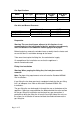
Wiring Diagram A N Part 8 240V AC Terminal Block Fuse - 3 Amp Transformer 240V AC - 110V AC 2A (50VA) Speed Control 240V AC 50 Hz Main Heater Supply High Limit Fan RFSDV34 GAS LOG FIRE WIRING DIAGRAM Page 22 of 27
Page 23 of 27
Page 24 of 27
Page 25 of 27
Part 9 Warranty RAYPAK RFSDV34RFN & RFSDV34RFP FREESTANDING GAS LOG FIRE WARANTY - AUSTRALIA ONLY – Rheem Australia * will: a) Repair or, if necessary replace any Raypak RFSDV34 Freestanding Gas Log Fire, or b) Replace any component (or, if necessary, arrange the installation of a Raypak Gas Log Fire, which falls within the Warranty Periods specified below, in accordance with and subject table, conditions and exclusions.
RAYPAK MAJESTIC RFSDV34RFNAU AND RFSD34RFPAU WARRANTY - AUSTRALIA ONLY – WARRANTY CONDITIONS 1. 2. 3. 4. 5. 6. This warranty is applicable only to the RFSDV34RFN and the RFSDV34RFP gas log fires manufactured from August 2005 The gas log fire must be installed in accordance with the Raypak installation instructions, supplied with the appliance and in accordance with all relevant statutory and local requirements of the State in which the appliance is installed.