
Installation guide

18 MK II Wheel Drive
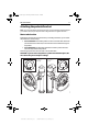
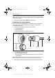
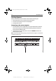
Horizontal alignment
When viewed from above (as shown in the illustration above):
• the sensor arm must be between 75 mm (3 in) and 310 mm (12 in) from the tiller arm
• with the rudder amidships, the sensor arm should be at 90° to the connecting rod and
directly opposite the cable entry point on the sensor body
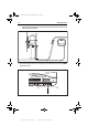
• when the rudder moves from hardover to hardover:
• the sensor arm and the tiller arm must remain parallel to each other at all times
• sensor arm movement must not exceed +/- 60°: if the steering system drives the sen-
sor arm beyond these limits it will damage the rudder position sensor
Maximum
permitted
travel: +/- 60˚
Cable entry
Parallel
Minimum: 75 mm (3 in)
Maximum: 310 mm (12 in)
90˚
60˚ 60˚
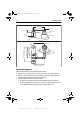
Min: 101 mm (4 in)
Optimum: 140 mm (5.5 in)
Max: 190 mm (7.5 in)
D8917-1
Mounting base
Tiller arm
or quadrant
Rudder position
sensor
Connecting rod
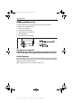
Ball joints (level)
Sensor arm
Parallel
Front view - rudder amidships
Top view - rudder amidships
Aft
87063_1.book Page 18 Monday, December 19, 2005 3:22 PM
www.Busse-Yachtshop.de email: info@busse-yachtshop.de