Distributed by Any reference to Raytheon or RTN in this manual should be interpreted as Raymarine. The names Raytheon and RTN are owned by the Raytheon Company.
81171_4.
81171_4.
81171_4.BOOK Page iii Thursday, November 29, 2001 11:34 AM Prelim Pages iii Raynav 300 GPS Plotter Owner’s Handbook SAFETY NOTICES WARNING: NAVIGATION AID This device is intended to be used as an aid to navigation. Its accuracy can be affected by many factors, including equipment failure or defects, environmental conditions and incorrect handling or use. It is the user’s responsibility to exercise common prudence and navigational judgement.
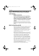
81171_4.BOOK Page iv Thursday, November 29, 2001 11:34 AM iv Raynav 300 GPS Plotter D4903-1 Figure i: The WAAS System Availability of the WAAS System in North America The WAAS system is presently broadcasting and being tested for aviation use. It is expected to be certified by the FAA in 2002. During this testing and certification period, continuous service is expected; however, brief signal outages may occur as refinements and upgrades are made to the system.
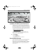
81171_4.BOOK Page v Thursday, November 29, 2001 11:34 AM Prelim Pages 135˚E 150˚E v 165˚E 180˚ 165˚W 150˚W 135˚W 120˚W 105˚W 90˚W 75˚W 60˚W 45˚W 30˚W 15˚W 0˚ 15˚E 75˚N 60˚N 45˚N 30˚N 15˚N 0˚ 15˚S D4910-1 Figure ii: WAAS Coverage Map Coverage Outside of North America Europe and Asia are developing similar systems to WAAS called EGNOS and MSAS respectively. Combined with WAAS, these systems will provide global satellite based differential GPS augmentation into the future.
81171_4.BOOK Page vi Thursday, November 29, 2001 11:34 AM vi Raynav 300 GPS Plotter Preface This handbook covers the Raynav 300 GPS Plotter manufactured by Raymarine. It contains important information on the installation and operation of your new equipment. In order to obtain the best results in operation and performance, please read this handbook thoroughly. Raymarine’s Product Support representatives or your authorized dealer are available to answer any questions you may have.
1171_4.BOOK Page vii Thursday, November 29, 2001 11:34 AM Prelim Pages vii Contents - Raynav 300 Plotter SAFETY NOTICES......................................................................... iii WAAS Satellite Differential GPS ............................................. iii Availability of the WAAS System in North America iv Extended Offshore Coverage iv Coverage Outside of North America v Accuracy and Continuation of Broadcast Coverage v Preface .....................................................
81171_4.BOOK Page viii Thursday, November 29, 2001 11:34 AM viii Chapter 3: Operation ..................................................................................3-1 3.1 Introduction..............................................................................3-1 3.2 Changing the Display Mode....................................................3-1 Data Display Pages ..................................................................3-2 GPS/Waypoint Data ................................................
81171_4.BOOK Page ix Thursday, November 29, 2001 11:34 AM Prelim Pages ix 3.8 Man Overboard (MOB) ........................................................3-44 3.9 Alarms & Timers...................................................................3-45 3.10 Cursor Echo...........................................................................3-47 Chapter 4: Setting Up the GPS Plotter .................................................... 4-1 4.1 Introduction...................................................
81171_4.BOOK Page x Thursday, November 29, 2001 11:34 AM x Registering this Product ..........................................................5-3 5.3 GPS Antenna Installation.........................................................5-4 Surface Mounting ....................................................................5-4 Pole Mounting .........................................................................5-6 5.4 Plotter Installation ....................................................................
81171_4.BOOK Page 1 Thursday, November 29, 2001 11:34 AM Chapter 1: Overview 1-1 Chapter 1: Overview 1.1 Introduction This handbook describes the Raynav 300 GPS Plotter. Note: Many illustrations in this handbook show example screens. The screen you see on your display depends on your system configuration and set up options, so it may differ from the illustration.
81171_4.BOOK Page 2 Thursday, November 29, 2001 11:34 AM 1-2 Raynav 300 GPS Plotter 1.2 Features General The Raynav 300 GPS Plotter has a built-in GPS that provides the following navigational signals: • • • Satellite Differential GPS (eg, WAAS). Ground based Differential GPS, when used with an additional RTCM beacon receiver. Standard GPS. These are listed in order of accuracy and their availability is dependent upon your location.
81171_4.BOOK Page 3 Thursday, November 29, 2001 11:34 AM Chapter 1: Overview 1-3 Those modes containing more than one page of data provide additional soft keys giving access to the sub-sets of data within each group, each cycled through with the associated soft key. 1.3 The Plotter Display When a position fix has been established, your vessel’s position, if on screen, is shown as a boat shape, pointing in the direction of the current heading (or COG if heading data is not available).
81171_4.
81171_4.BOOK Page 5 Thursday, November 29, 2001 11:34 AM Chapter 1: Overview 1-5 1.4 Operating Controls Operation utilizes a number of buttons and on-screen controls. These include: • • • • • A trackpad providing up, down, left, right and diagonal control of an on-screen cursor. Eight dedicated (labelled) control keys. Four soft keys with labels displayed on screen. Pop-up menus, displayed on-screen, from which options are selected. Database lists, displayed on-screen, which enable editing of items.
81171_4.BOOK Page 6 Thursday, November 29, 2001 11:34 AM 1-6 Raynav 300 GPS Plotter The cursor is used to: • • • • Select a position on the screen. Select and, if valid, move an item, e.g. a waypoint, on the screen. Select an area of the screen to zoom into. Pan the display. Moving the Cursor Press the corresponding edge of the trackpad to move the cursor horizontally, vertically or diagonally; the longer you press, the faster the cursor moves.
81171_4.BOOK Page 7 Thursday, November 29, 2001 11:34 AM Chapter 1: Overview 1-7 Dedicated Keys The dedicated keys: DISPLAY, MARK, RANGE, ALARMS, ENTER, CLEAR, MENU and POWER have fixed functions. Some keys can be used in two ways: • • Press: Press the key momentarily and then release it. This method is used for most key operations. Press and hold: Press the key and hold it down for the length of time stated (for example, 3 seconds), then release it.
81171_4.BOOK Page 8 Thursday, November 29, 2001 11:34 AM 1-8 Raynav 300 GPS Plotter Pop-Up Menus Pop-up menus usually provide set up options. When a pop-up menu is on-screen, a set of associated soft keys is also displayed as shown in Figure 1-3. ALARMS SET UP ARRIVAL ALARM OFF TRACK ALARM ANCHOR ALARM COUNTDOWN TIMER ALARM CLOCK 0.
81171_4.BOOK Page 1 Thursday, November 29, 2001 11:34 AM Chapter 2: Getting Started 2-1 Chapter 2: Getting Started 2.1 Introduction This chapter provides information, instructions and a simple familiarization exercise in using the display. Operating information is detailed in Chapter 3. Conventions Used Throughout this handbook, the dedicated (labelled) keys are shown in bold capitals; for example, ENTER. The soft key functions, menu names and options are shown in normal capitals; for example, SCREEN.
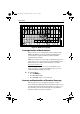
81171_4.BOOK Page 2 Thursday, November 29, 2001 11:34 AM 2-2 Raynav 300 GPS Plotter GPS STATUS SAT SIGNAL STATUS SAT SIGNAL STATUS LOCKED 23 LOCKED 15 IN USE 18 IN USE 09 IN USE 26 IN USE 08 LOCKED 12 LOCKED 10 LOCKED 14 LOCKED 20 LOCKED 03 LOCKED 17 FIX MODE GPS D SD HDOP FIX STATUS 1.0 D-FIX D-GPS SET UP RESTART GPS D5551_1 Figure 2-1: GPS Status Screen The GPS Status screen is displayed until a satellite fix has been acquired.
81171_4.BOOK Page 3 Thursday, November 29, 2001 11:34 AM Chapter 2: Getting Started 2-3 zero the display and key backlights extinguish. If the POWER key is released within this period, power-down is cancelled. Changing the Lighting and Contrast You can change the level of backlighting and contrast for the screen and keys. The key backlighting always retains a minimal level to enable the keys to be seen at night. ➤ To change the lighting and contrast: 1.
81171_4.BOOK Page 4 Thursday, November 29, 2001 11:34 AM 2-4 Raynav 300 GPS Plotter ROUTE GOTO SCREEN FIND SHIP D4897-1 Figure 2-4: Default Soft Keys On completion of an action using the soft keys, press CLEAR to return to the default screen; you may need to press CLEAR several times to back-track through the soft key hierarchy. Note: If you have set up your system so that the default soft keys are not permanently displayed, press any soft key to display the labels.
81171_4.BOOK Page 5 Thursday, November 29, 2001 11:34 AM Chapter 2: Getting Started 2-5 Press POWER ... after preliminary displays, the default display is shown OWN POS XTE XTE SD-FIX SD-FIX SD-FIX SD-FIX SD-FIX SD-FIX GPS data SD-FIX Waypoint data 320°M XTE WPT BRG WPT RNG WPT BRG WPT BRG 0.55nm 352°M COG SOG WPT RNG 050°M SOG 0.55nm SOG STEER STARBOARD COG SOG WPT DATA WPT 004 12.
81171_4.BOOK Page 6 Thursday, November 29, 2001 11:34 AM 2-6 Raynav 300 GPS Plotter 2.4 Plotter Display Control Functions You will normally operate the GPS Plotter with the display showing one of the Navigation Data pages. The range of pages is listed in Selecting the Display Mode on page 2-4 and illustrated in Figure 2-5. The complete range of pages is described fully in Data Display Pages on page 3-2.
81171_4.BOOK Page 7 Thursday, November 29, 2001 11:34 AM Chapter 2: Getting Started 2-7 ➤ To release the cursor from homed mode, use the trackpad to move the cursor away from the vessel’s current position. The status bar shows the current cursor position, bearing and range. The cursor no longer moves with the vessel and no redraw occurs if the vessel moves off screen. Changing the Display Center You can move the area of the display center using the context-sensitive cursor.
81171_4.BOOK Page 8 Thursday, November 29, 2001 11:34 AM 2-8 Raynav 300 GPS Plotter 6nm VES 43°27^05N POS 001°02^83W SOG 23.4kts COG 234°M D4902-1 Figure 2-6: Status Bar ➤ To change the scale rapidly, press and hold top or bottom of the RANGE key. The distance indicator at the left-hand side of the status bar is updated whenever you change the display scale. ➤ To zoom in to a larger-scale (more detailed) display: 1. Use the trackpad to position the cursor in the area you wish to see in larger scale.
81171_4.BOOK Page 9 Thursday, November 29, 2001 11:34 AM Chapter 2: Getting Started 2-9 Switching Grid On/off The Plotter display can be set to show grid lines of latitude and longitude which can help determine position. ➤ To turn the grid on or off: 1. Press the SCREEN default soft key. 2. Press the CHRT GRID soft key to toggle the setting ON and OFF. 3. To return to the default soft key display, press CLEAR.
81171_4.
81171_4.BOOK Page 1 Thursday, November 29, 2001 11:34 AM Chapter 3: Operation 3-1 Chapter 3: Operation 3.1 Introduction This chapter explains how to navigate with the Raynav 300 GPS Plotter. It covers the following topics: • • • • • • • • • Controlling waypoints, including placing, moving, editing and deleting waypoints. Changing the display mode. • Using a range of data pages to display navigation data. • Maintaining a Data Log of Time, Position, Course Made Good (CMG) and Distance Made Good (DMG).
81171_4.BOOK Page 2 Thursday, November 29, 2001 11:34 AM 3-2 Raynav 300 GPS Plotter The modes that contain more than one page of data provide additional soft keys which cycle through the pages. The highlighted soft key indicates the screen mode currently displayed. Note: Press the DISPLAY key for at least two seconds in any display mode to return to the GPS/Waypoint display. Data Display Pages In all graphical display pages, the steering instruction is STEER STARBOARD if the XTE is 0.
81171_4.BOOK Page 3 Thursday, November 29, 2001 11:34 AM Chapter 3: Operation 3-3 GPS/Waypoint Data GPS Data The GPS Data display comprises four text data pages, selected in turn by the GPS DATA soft key. These pages are shown in Figure 3-1 to Figure 3-4. WPT BRG SD-FIX 320°M 50°50^000N 0.55 001°50^000W 050° WPT RNG nm COG STEER STARBOARD WPT 004 ROUTE GOTO M SOG 12.0kts GPS DATA WPT DATA D4936-2 Figure 3-1: GPS Data Page #1 WPT BRG SD-FIX 320°M SOG 12.5kts COG 320°M WPT RNG 0.
81171_4.BOOK Page 4 Thursday, November 29, 2001 11:34 AM 3-4 Raynav 300 GPS Plotter WPT BRG SD-FIX 320°M 12:34:00 23/02/00 0.55nm WPT 004 12.
81171_4.BOOK Page 5 Thursday, November 29, 2001 11:34 AM Chapter 3: Operation 3-5 Waypoint Data The Waypoint Data display comprises three data pages, selected in turn by the WPT DATA soft key. These pages are shown in Figure 3-5 to Figure 3-7: XTE SD-FIX 320°M RNG 0.55nm BRG STEER STARBOARD WPT 004 ROUTE GOTO 0.06nm TTG 01h:00m COG 050°M SOG 12.0kts GPS DATA WPT DATA D4940-2 Figure 3-5: Waypoint Data #1 XTE SD-FIX 320°M RNG 0.55nm BRG 0.
81171_4.BOOK Page 6 Thursday, November 29, 2001 11:34 AM 3-6 Raynav 300 GPS Plotter OWN POS SD-FIX 320°M RNG 0.55nm BRG STEER STARBOARD WPT 004 ROUTE GOTO 50°50^000N 001°06^000W WPT POS 50°50^000N 001°06^000W COG 050°M SOG 12.0kts GPS DATA WPT DATA D4942-2 Figure 3-7: Waypoint Data #3 Boat/Environment Data Boat Data The Boat Data display comprises three data pages, selected in turn by the BOAT DATA soft key. These pages are shown in Figure 3-8 to Figure 3-10: WPT BRG SD-FIX 12.
81171_4.BOOK Page 7 Thursday, November 29, 2001 11:34 AM Chapter 3: Operation 3-7 WPT BRG SD-FIX 320°M 12.5M TEMP 11°C WPT RNG DEPTH STEER STARBOARD WPT 004 ROUTE GOTO 0.55nm COG 050°M SOG 12.0kts BOAT DATA ENVIROMNT D4944-2 Figure 3-9: Boat Data #2 PILOT SD-FIX 325°M LOCK 323°M HDG STEER STARBOARD WPT 004 ROUTE GOTO AUTO RUDDER --COG 050°M XTE 0.
81171_4.BOOK Page 8 Thursday, November 29, 2001 11:34 AM 3-8 Raynav 300 GPS Plotter Environment Data The Environment Data display comprises two data pages, selected in turn by the ENVIRONMT soft key. These pages are shown in Figure 3-11 and Figure 3-12. WIND WIND (TRUE) 105°STBD 32.0 kts STEER STARBOARD WPT 004 ROUTE GOTO SSW 7 RUDDER --COG 050°M HEADING 320°M BOAT DATA ENVIROMNT D4946-2 Figure 3-11: Environment Data #1 WIND WIND (APP) 105°STBD 32.
81171_4.BOOK Page 9 Thursday, November 29, 2001 11:34 AM Chapter 3: Operation 3-9 CDI/BDI Data The Course Deviation Indicator (CDI) / Bearing Deviation Indicator (BDI) display comprises two data pages, selected alternately by the CDI and BDI soft keys. These pages are shown in Figure 3-13 and Figure 3-14: CDI Data The CDI display shows Cross Track Error (XTE) and Distance to Waypoint presented in a ‘runway’ format as shown in Figure 3-13: XTE 355°T 0.05nm WPT BRG 300°T WPT RNG 23.
81171_4.BOOK Page 10 Thursday, November 29, 2001 11:34 AM 3-10 Raynav 300 GPS Plotter of distance to destination and Velocity Made Good (VMG) towards destination. XTE 225°T 0.05nm 40 WPT BRG 40 30 300°T 30 WPT RNG 20 20 nm 23.2nm nm 10 10 TTG STEER STARBOARD WPT 004 ROUTE GOTO 04h:12m CDI BDI D4933-2 Figure 3-14: BDI Display The line to the waypoint symbol is shown at an angle equal to the difference between the COG and the Bearing to Waypoint to a maximum of ±15°.
81171_4.BOOK Page 11 Thursday, November 29, 2001 11:34 AM Chapter 3: Operation 3-11 Data Log The GPS Plotter can be set to log passage data every 30 minutes. Up to 48 log entries are held. When 48 entries have been saved, the first entries start being overwritten. If the number of log entries exceeds the table size, use the trackpad up/down to scroll the list and view further log entries.
81171_4.BOOK Page 12 Thursday, November 29, 2001 11:34 AM 3-12 Raynav 300 GPS Plotter 3.3 Working with Waypoints Introduction You can place up to 998 waypoints on the GPS Plotter. A waypoint is a position entered on the display as a reference or destination point. All waypoints placed on the GPS Plotter are stored in a waypoint database list which includes symbol, position, bearing, range and additional data.
81171_4.BOOK Page 13 Thursday, November 29, 2001 11:34 AM Chapter 3: Operation 3-13 Placing a Waypoint ➤ To access the Place Waypoint soft keys, press MARK; the Place Waypoint soft keys are displayed as shown in Figure 3-17: PLACE WPT PLACE WPT AT CURSOR AT VESSEL WAYPOINT LIST D4905-1 Figure 3-17: Waypoint Soft Keys ➤ To place a waypoint at the cursor (plotter screen) or the vessel’s current position: 1. Press either the PLACE WPT AT CURSOR or the PLACE WPT AT VESSEL soft key.
81171_4.BOOK Page 14 Thursday, November 29, 2001 11:34 AM 3-14 Raynav 300 GPS Plotter 2. Press the MAKE NEW WAYPOINT soft key; the New Waypoint screen is displayed, together with its associated soft keys, see Figure 3-19. NEW WAYPOINT SYMBOL NAME WPT 005 POSITION N 50°50^000 W 001°06^000W BRG SYMBOL 124°m NAME RNG 12.6nm LAT/LONG LORAN TDs D5518-1 Figure 3-19: New Waypoint Screen 3.
81171_4.BOOK Page 15 Thursday, November 29, 2001 11:34 AM Chapter 3: Operation 3-15 WPT POSITION (LORAN TDs) CHAIN SLAVES TD 1 TD 2 ASF 1 ASF 2 CHAIN 6731 - NELS Lessay Y - Z (24 -39) 29138.0 us 44713.8 us +0.0 +0.0 ASF1/ASF2 SET TD 1 SET TD 2 D5519-1 Figure 3-20: Waypoint Position Screen (Loran TDs) Note: You can enter Waypoints as Loran TDs which are converted to Lat/Long coordinates. You can subsequently only edit their positions as Lat/Long coordinates. 3.
81171_4.BOOK Page 16 Thursday, November 29, 2001 11:34 AM 3-16 Raynav 300 GPS Plotter iii. the SET TD 1 and SET TD 2 soft keys, which enable editing of each TD’s co-ordinate values. Note: Except for the CHAIN setting, numerical data is edited using the trackpad as described in Editing Waypoint Details on page 3-18. 4. When editing is complete, press ENTER to save the waypoint details. (or CLEAR to cancel the operation); the display returns to the New Waypoint screen. 5.
81171_4.BOOK Page 17 Thursday, November 29, 2001 11:34 AM Chapter 3: Operation 3-17 Selecting a Waypoint Selecting a waypoint from the Waypoint List allows you to GOTO and EDIT (symbol, name, position, erase) the waypoint. The Waypoint List also provides options to make a new waypoint and transfer waypoints. Positioning the cursor over a waypoint selects that waypoint and accesses the waypoint soft keys.
81171_4.BOOK Page 18 Thursday, November 29, 2001 11:34 AM 3-18 Raynav 300 GPS Plotter 2. To remove the Waypoint List and return to the default soft key display, press CLEAR twice. ➤ To display the Waypoint Data Box: 1. Move the cursor over the waypoint. • The Waypoint Data Box is displayed which indicates waypoint number/name, bearing and range (or lat/lon if selected in the system set up menu, see System Set Up Parameters on page 4-2).
81171_4.BOOK Page 19 Thursday, November 29, 2001 11:34 AM Chapter 3: Operation 3-19 The NAME WAYPOINT window is displayed. 5. Use the trackpad to enter or edit the name: • Use the trackpad left/right to move the cursor to the character to be changed. • Use the trackpad top/bottom to scroll through the characters. 6. When name editing is complete, press ENTER to save the name and remove the window, or CLEAR to cancel the operation. The waypoint name replaces the waypoint number. 7.
81171_4.BOOK Page 20 Thursday, November 29, 2001 11:34 AM 3-20 Raynav 300 GPS Plotter 3. If the the deleted waypoint was the only waypoint in the list, the default soft keys are displayed, otherwise, press CLEAR three times to return to the default soft keys. ➤ To delete a waypoint using the cursor: 1. Move the cursor over the waypoint until the letters WPT are displayed. The waypoint soft keys are displayed. 2. Press the ERASE WAYPOINT soft key.
81171_4.BOOK Page 21 Thursday, November 29, 2001 11:34 AM Chapter 3: Operation 3-21 3.4 Working with Routes A route is made up of a series of waypoints (maximum 50). To make a route you place a series of waypoints and/or use existing ones. When a route is created, it becomes the current route and is displayed on screen. The current route is maintained when you power-off. Only one route can be current and is displayed (if in the field-of-view) as solid lines connecting waypoints.
81171_4.BOOK Page 22 Thursday, November 29, 2001 11:34 AM 3-22 Raynav 300 GPS Plotter Creating a New Route Note: If there is a current route, it is cleared when MAKE ROUTE is selected. If following the current route you are prompted to STOP FOLLOW. Press the YES soft key to continue, or NO to abandon route creation. If the route has not been saved you are prompted to save it.
81171_4.BOOK Page 23 Thursday, November 29, 2001 11:34 AM Chapter 3: Operation 3-23 The Route Building Table shows available Waypoints in the left hand column (in alphanumeric order). The right hand column contains the waypoints in the New Route. The number to the left of the waypoint name in the New Route column indicates its order in the route. The lower part of the table shows position, bearing and range of the highlighted waypoint. 3.
81171_4.BOOK Page 24 Thursday, November 29, 2001 11:34 AM 3-24 Raynav 300 GPS Plotter 4. Press the MAKE ROUTE soft key; the make route soft keys are displayed as shown in Figure 3-30. PLACE WAYPOINT UNDO WAYPOINT ACCEPT ROUTE USE WPT LIST D4928-1 Figure 3-30: Make Route Soft Keys 5. Move the cursor to the position on the plotter where the first waypoint is to be placed, then press the PLACE WAYPOINT soft key; the new waypoint appears on the screen at the cursor position.
81171_4.BOOK Page 25 Thursday, November 29, 2001 11:34 AM Chapter 3: Operation 3-25 Saving the Current Route You can save up to 20 named routes in the Route Database List. These routes can then be re-displayed and followed at a later date. When you save the route, all new waypoints are saved in the Waypoint List. Note: When a change to this route is attempted, eg. CLEAR ROUTE and the current route has not been saved, you are prompted to save it. ➤ To save and name the current route: 1.
81171_4.BOOK Page 26 Thursday, November 29, 2001 11:34 AM 3-26 Raynav 300 GPS Plotter Displaying Route Information The following route information can be displayed: • • Full route details, using the soft keys. Route leg or waypoint information, using the context-sensitive cursor. Full Route Details ➤ To display information about any route in the database: 1. Press the ROUTE soft key, followed by MORE, then press ROUTE LIST.
81171_4.BOOK Page 27 Thursday, November 29, 2001 11:34 AM Chapter 3: Operation 3-27 INFO FOR ROUTE - NEW ROUTE WPT POSITION 01 02 BRG DISTANCE TOTAL TIME °T nm nm ETA --0.0 0.0 0:00 50°50^00N 001°06^00W 50°51^00N 239 001°07^00W TIME: 14:03:39 TIME ETA HOURS ACTUAL SOG 4.5kts 4.8 4.8 0:20 DATE: 10/29/2001 PLANNED SOG 6.1kts D4930-3 Figure 3-33: Route Information Screen 3.
81171_4.BOOK Page 28 Thursday, November 29, 2001 11:34 AM 3-28 Raynav 300 GPS Plotter Route Leg and Waypoint Information ➤ To display information about a route leg, move the cursor over the leg until the letters RTE appear. The Route Leg data box is displayed, together with the Follow Route soft keys as shown in Figure 3-34. ROUTE 01 ROUTE NOT NAMED LEG 02 - 03 270°T 13.
81171_4.BOOK Page 29 Thursday, November 29, 2001 11:34 AM Chapter 3: Operation 3-29 Press the CLEAR ROUTE soft key to clear the route. or... 2. Press the ROUTE default soft key. The Route soft keys are displayed as shown in Figure 3-29: Press the CLEAR ROUTE soft key to clear the route. or... 3. If following the current route, the STOP FOLLOW soft keys are displayed as shown in Figure 3-36. ROUTE 01 ROUTE NOT NAMED LEG 02 - 03 270°T 13.
81171_4.BOOK Page 30 Thursday, November 29, 2001 11:34 AM 3-30 Raynav 300 GPS Plotter ➤ To select a route as the current route: 1. From plotter mode, press the ROUTE soft key, followed by MORE, then ROUTE LIST. The Route List is displayed with the selected route highlighted, see Figure 3-32. Note: In any mode other than plotter mode, the ROUTE LIST soft key is available without pressing the MORE... soft key. 2. Use the trackpad up/down to select the required route then press the SHOW ROUTE soft key.
81171_4.BOOK Page 31 Thursday, November 29, 2001 11:34 AM Chapter 3: Operation 3-31 Note: Apart from Moving a Waypoint used in other route(s), any changes made to the route affect the current route only. The current route must always be Saved in order to keep the changes. Inserting a Waypoint into a Route The context-sensitive cursor can be used to insert one or more waypoints into the current route. However, if the route is being followed, a waypoint cannot be inserted into the current leg.
81171_4.BOOK Page 32 Thursday, November 29, 2001 11:34 AM 3-32 Raynav 300 GPS Plotter Removing a Waypoint from within the Route ➤ To remove a waypoint from within the current route: 1. Move the cursor over the required waypoint until the letters WPT appear; the waypoint soft keys are displayed. 2. Press the REMOVE WAYPOINT soft key. The waypoint is removed from the route and the route is re-numbered.
81171_4.BOOK Page 33 Thursday, November 29, 2001 11:34 AM Chapter 3: Operation 3-33 intended track, from your start point or previous waypoint, to the target waypoint. This section describes the following: • • • • • Go to an individual target point (an existing waypoint or the cursor). Follow a route either forward, or reversed. Joining a route at a selected waypoint, advancing to waypoints or restarting XTE. Stop and Restart Follow/Goto.
81171_4.BOOK Page 34 Thursday, November 29, 2001 11:34 AM 3-34 Raynav 300 GPS Plotter 3. To return to the default soft key display, move the cursor away from the waypoint or press CLEAR. ➤ To navigate directly to the cursor position: 1. Use the trackpad to position the cursor as required. 2. Press the GOTO default soft key, followed by GOTO CURSOR. If navigation is currently in progress you are warned ALREADY FOLLOWING ROUTE. CANCEL ROUTE AND GOTO CURSOR? i.
81171_4.BOOK Page 35 Thursday, November 29, 2001 11:34 AM Chapter 3: Operation STOP FOLLOW 3-35 GOTO CURSOR RESTART XTE WAYPOINT ADVANCE D4914-1 Figure 3-39: Follow Route Soft Keys ➤ To follow the current route in reverse using the soft keys: 1. Reverse the route as described in Reversing the Route on page 3-32. 2. Press the GOTO default soft key; the Goto/Follow soft keys are displayed. 3. Press the FOLLOW ROUTE soft key. ➤ To follow the current route in reverse using the cursor: 1.
81171_4.BOOK Page 36 Thursday, November 29, 2001 11:34 AM 3-36 Raynav 300 GPS Plotter ➤ To advance to a waypoint: 1. Press the GOTO default soft key to display the Goto/Follow soft keys. 2. Press the WAYPOINT ADVANCE soft key. The current leg of the route is abandoned and the next waypoint becomes the target. The display is updated to show the new route leg. Note: You can advance past the end of a route back to the start.
81171_4.BOOK Page 37 Thursday, November 29, 2001 11:34 AM Chapter 3: Operation • • 3-37 The distance to the target point is less than that specified for the Arrival alarm. Your vessel reaches the closest point of approach to the target (defined by an imaginary circle around the waypoint). ➤ To cancel the Arrival alarm and go towards the next waypoint in the route, either: • Press any key or... • Wait for 10 seconds.
81171_4.BOOK Page 38 Thursday, November 29, 2001 11:34 AM 3-38 Raynav 300 GPS Plotter • When this option is selected, any waypoints received on SeaTalk or NMEA are transferred and appended, one-by-one, to the Waypoint List. Routes received on NMEA are appended to the Route List.You can use this function to add waypoints from a PC connected via NMEA. You can send the Waypoint and Route Lists from the display unit to other instruments via NMEA using the SEND WPT LIST function.
81171_4.BOOK Page 39 Thursday, November 29, 2001 11:34 AM Chapter 3: Operation 3-39 While Track is on, it is recorded in memory as the Current Track and is retained following a POWER OFF/ON. You specify the interval at which track points are created and a line is drawn on-screen between each point. The current track remains on-screen until you clear the track.
81171_4.BOOK Page 40 Thursday, November 29, 2001 11:34 AM 3-40 Raynav 300 GPS Plotter Refer to the setting guide shown in Figure 3-40 to determine the best setting for your planned voyage; this is particularly important if you wish to use SmartRoute to convert your track to a route.
81171_4.BOOK Page 41 Thursday, November 29, 2001 11:34 AM Chapter 3: Operation 3-41 3. Press the MORE... soft key to display the second level Track soft keys as shown in Figure 3-43. TRACK INTERVAL 1S TRACK LIST MORE¬ D4920-1 4. 5. 6. 7. Figure 3-43: Second Level Track Soft Keys Press the appropriate TRACK INTERVAL up/down soft key to set an appropriate TIME or DISTANCE interval. Press MORE to return to the first level Track soft keys. Press the TRACK OFF ON soft key to toggle tracks on/off.
81171_4.BOOK Page 42 Thursday, November 29, 2001 11:34 AM 3-42 Raynav 300 GPS Plotter 2. Check the route and, in particular, that the route deviation from the original, given in the warning box, is within navigable limits. Managing Tracks It is a staightforward task to set up a Current Track which is retained even if you switch off your display unit. In addition, up to five different tracks can be saved so that you can use them at a later date.
81171_4.BOOK Page 43 Thursday, November 29, 2001 11:34 AM Chapter 3: Operation 3-43 Naming, Erasing and Showing a Track ➤ To name an existing track, erase a track or show a track: 1. Press the TRACK LIST soft key; the Track List is displayed. The highlight indicates the selected track. 2. Using the trackpad top/bottom, select the required track and press the SAVE TRACK, NAME TRACK or ERASE TRACK soft key. 3.
81171_4.BOOK Page 44 Thursday, November 29, 2001 11:34 AM 3-44 Raynav 300 GPS Plotter 3.8 Man Overboard (MOB) If a person or object is lost overboard, use the Man Overboard (MOB) function to return to the location immediately. Note: To obtain an MOB position, you need either of the following: • • Position data from the GPS antenna. Heading and speed data, so that the position can be calculated by dead reckoning.
81171_4.BOOK Page 45 Thursday, November 29, 2001 11:34 AM Chapter 3: Operation • 3-45 Replaces all current waypoint data with MOB data. ➤ To cancel the MOB, press and hold the MARK key for 2 seconds. The chart is re-drawn at its previous scale, and the MOB symbol and data box are removed. Note: The MOB procedure can also be initiated or cancelled remotelyfrom other Raymarine equipment connected via SeaTalk. 3.
81171_4.BOOK Page 46 Thursday, November 29, 2001 11:34 AM 3-46 Raynav 300 GPS Plotter Setting Alarms and Timers ➤ To set up an alarm or timer: 1. Press the ALARMS key. The Alarms Set Up list is displayed, showing the current settings as shown in Figure 3-46. ALARMS SET UP ARRIVAL ALARM OFF TRACK ALARM ANCHOR ALARM COUNTDOWN TIMER ALARM CLOCK ALARM OFF ON 0.01nm ON OFF 00:10:00 OFF SELECT DISTANCE D4898_2 2. 3. 4. 5.
81171_4.BOOK Page 47 Thursday, November 29, 2001 11:34 AM Chapter 3: Operation 3-47 3.10 Cursor Echo In a plotter display, or in a system with any plotter display connected via Seatalk, you can set the display to enable cursor transfer. Cursor echo is accessed from the Set Up Menu and enables the display of a plotter cursor on other equipment, or another equipment’s cursor on the plotter display. Refer to Chapter 4 to set up cursor echo.
81171_4.
81171_4.BOOK Page 1 Thursday, November 29, 2001 11:34 AM Chapter 4: Setting Up the GPS Plotter 4-1 Chapter 4: Setting Up the GPS Plotter 4.1 Introduction When you have installed your system and are familiar with its basic operation, you may wish to set it up to operate according to your requirements and display information according to your preferences. This is achieved using the Set Up controls which are displayed when you press the MENU key. These settings can be changed at any time.
81171_4.BOOK Page 2 Thursday, November 29, 2001 11:34 AM 4-2 Raynav 300 GPS Plotter As each line is highlighted, the soft keys are updated to show the settings available. • For parameters that have a numeric value, or more than four possible settings, a scroll list is displayed above two of the soft keys. • Some parameters are controlled by an adjustable slider that is displayed above two of the soft keys. • For some parameters, a soft key provides access to a sub-menu of further options. 4.
81171_4.
171_4.BOOK Page 4 Thursday, November 29, 2001 11:34 AM 4-4 Raynav 300 GPS Plotter Table 4-1: System Set Up Parameters (Continued) Factory Default Menu Options LANGUAGE English (UK), English (US), Danish, French, German, Dutch, Icelandic, Italian, Norwegian, Portuguese, Spanish, Swedish, Finnish English (US) Simulator OFF or ON OFF New Default Bearing Mode This is the mode (magnetic or true) of all the bearing and heading data displayed as indicated in the status bar.
81171_4.BOOK Page 5 Thursday, November 29, 2001 11:34 AM Chapter 4: Setting Up the GPS Plotter 4-5 Help When Help is set to ON, a prompt appears in place of the status bar when selecting a soft key or menu choice and when using the context-sensitive cursor. The help message is cleared when an action is selected. Soft Keys When the Soft Keys option is set to ON, the default soft keys are displayed if no other operation is in progress.
81171_4.BOOK Page 6 Thursday, November 29, 2001 11:34 AM 4-6 Raynav 300 GPS Plotter Auto Mode If Auto mode is selected, the value of variation is obtained automatically, normally from received data. The variation value that is used depends on the data available, and is selected in the following order of priority: 1. Variation value from the same source as the heading data: If heading data is being taken from NMEA, then variation is also taken from NMEA.
81171_4.BOOK Page 7 Thursday, November 29, 2001 11:34 AM Chapter 4: Setting Up the GPS Plotter 4-7 Press the CURSOR ECHO soft key to display the cursor transfer soft keys. The following options can be toggled ON or OFF: • • • Radar Cursor In: displays the cursor from another radar on the plotter display or chart window (default - OFF). Chart Cursor In: displays the cursor from another plotter or chartplotter (default - OFF).
81171_4.BOOK Page 8 Thursday, November 29, 2001 11:34 AM 4-8 Raynav 300 GPS Plotter NMEA Input Select the NMEA input setting as appropriate. This can be set to either NMEA or RTCM. RTCM input is 4800 baud only. Language Select the language in which you wish information to be displayed. The selected language will be used for screen text, labels, menus and options, but will not affect the letters displayed by the context-sensitive cursor.
81171_4.BOOK Page 9 Thursday, November 29, 2001 11:34 AM Chapter 4: Setting Up the GPS Plotter 4-9 Factory Default Parameter Options HEADING VECTOR OFF, 3 MINS, 10 MINS INFINITE OFF COG VECTOR OFF, 3 MINS, 10 MINS INFINITE OFF TIDE VECTOR OFF, 10 MINS, 1 HOUR INFINITE OFF DATUM SELECTION WGS 84, LOCAL WGS 84 New Default Chart Orientation The plotter orientation is normally North Up, but can be changed to Course Up or Head Up if heading data is available.
81171_4.BOOK Page 10 Thursday, November 29, 2001 11:34 AM 4-10 Raynav 300 GPS Plotter Default Waypoint Symbol This setting provides a selection of symbols for the default waypoint display. Vectors Heading, Tide and Course Over Ground vectors can be displayed as a line from your vessel. The length of the vector is determined by your choice of SOG and the time period. An infinite vector extends to the edge of the screen. • • • Heading Vector indicates your current heading.
81171_4.BOOK Page 11 Thursday, November 29, 2001 11:34 AM Chapter 4: Setting Up the GPS Plotter 4-11 GPS STATUS SAT SIGNAL STATUS SAT SIGNAL STATUS LOCKED 23 LOCKED 15 IN USE 18 IN USE 09 IN USE 26 IN USE 08 LOCKED 12 LOCKED 10 LOCKED 14 LOCKED 20 LOCKED 03 LOCKED 17 FIX MODE GPS D SD HDOP FIX STATUS 1.
81171_4.BOOK Page 12 Thursday, November 29, 2001 11:34 AM 4-12 Raynav 300 GPS Plotter D-GPS Set Up The D-GPS SET UP function is only available when a Differential GPS receiver is connected and the unit is set as a GPS Source repeater (see GPS Source on page 4-7). It provides the ability to set up an external Differential GPS, either automatically (default) or by manually retuning it to a different differential beacon.
81171_4.BOOK Page 13 Thursday, November 29, 2001 11:34 AM Chapter 4: Setting Up the GPS Plotter 4-13 Beacon Frequency Both the menu item and associated soft keys show the currently used differential beacon’s frequency in kHz. In AUTO mode, this is the frequency received from the beacon receiver and the soft keys are disabled and grayed out. In MAN mode, this frequency is the user selected value which is sent via SeaTalk/NMEA to the beacon receiver.
81171_4.
81171_4.BOOK Page 1 Thursday, November 29, 2001 11:34 AM Chapter 5: Installation 5-1 Chapter 5: Installation 5.1 Introduction This chapter provides instructions to assist in planning the installation of the Raynav 300 GPS Plotter aboard your vessel. Note: If you wish to practice using the Raynav 300 GPS Plotter before installation, you can connect it, via a 1A quick blow fuse, to a 12VDC power supply and operate it using the simulator mode, as described in Chapter 2: Getting Started.
81171_4.BOOK Page 2 Thursday, November 29, 2001 11:34 AM 5-2 Raynav 300 GPS Plotter • Raymarine specified cables are used. Cutting and rejoining these cables can compromise EMC performance and must be avoided unless doing so is detailed in the installation manual. • If a suppression ferrite is attached to a cable, this ferrite should not be removed. If the ferrite needs to be removed during installation it must be reassembled in the same position.
81171_4.BOOK Page 3 Thursday, November 29, 2001 11:34 AM Chapter 5: Installation 5-3 5.2 Unpacking and Inspecting the Components Unpack your Raynav 300 GPS Plotter carefully. Retain the carton and packing materials in the event that you need to return the unit for service: System Parts and Accessories Item Part No.
81171_4.BOOK Page 4 Thursday, November 29, 2001 11:34 AM 5-4 Raynav 300 GPS Plotter 5.3 GPS Antenna Installation The GPS Antenna is designed to receive the signals emitted from the satellites in a direct path. Ideally, the unit should be mounted horizontally in a location that is open and clear of any masts or other structures that could block line-of-sight reception of signals. The height of the GPS Antenna is not as important as it’s having a clear view horizon to horizon for optimum signal reception.
81171_4.BOOK Page 5 Thursday, November 29, 2001 11:34 AM Chapter 5: Installation 5-5 mounting surface, remove the two plastic tabs (1) obstructing the cable channel. Note: Failure to remove the plastic tabs from within the cable channel could result in cable damage. 3. Screw the supplied brass studs (2) into the underside of the GPS Antenna. 4. Affix the supplied gasket (3) to the mounting surface ensuring that the holes match and pass the cable through the centre hole or the cable exit channel. 5.
81171_4.BOOK Page 6 Thursday, November 29, 2001 11:34 AM 5-6 Raynav 300 GPS Plotter Pole Mounting ➤ Refer to Figure 5-3: 1. Screw the pole mount base to a suitable pole or rail mount bracket, having an industry standard 1inch 14TPI thread, until secure. 2. Pass the cable through the centre hole of the pole mount base (A) or insert the cable into the side exit channel (B). 3. Check that the cable is positioned correctly and secure the GPS Antenna to the pole mount base using the two screws provided.
81171_4.BOOK Page 7 Thursday, November 29, 2001 11:34 AM Chapter 5: Installation 5-7 5.4 Plotter Installation The display unit can be mounted using the trunnion (yoke) bracket, or panel mounted using the optional Panel Mounting Kit. When planning the installation of your Raynav 300, the following points should be considered: • Convenience: The unit should be installed in a convenient position where it can be viewed straight on or with a viewing angle of less than 35°.
81171_4.BOOK Page 8 Thursday, November 29, 2001 11:34 AM 5-8 Raynav 300 GPS Plotter 3.9 in (99 mm) 9.13 in (232 mm) 3.07 in (78 mm) 1.2 in (31 mm) 7.67 in (195 mm) 3.15 in (80 mm) 0.5 in 1 in (25 mm) 3.5 in (89 mm) (12 mm) 4.8 in (122 mm) 4.33 in (110 mm) plug clearance 2 in 2 in (51 mm) (51 mm) 6.9 in (175 mm) 7.
81171_4.BOOK Page 9 Thursday, November 29, 2001 11:34 AM Chapter 5: Installation 5-9 4. Secure the gasket to the rear of the unit: Remove the protective paper from the adhesive side of the gasket (this is the side that is to be affixed to the unit) then press the gasket onto the rear case, covering the screws. 5. Fit the unit to the trunnion, adjust the display angle and tighten the knobs. 6. Connect the Power/NMEA and GPS cables to the unit, avoiding tight bends in the cables.
81171_4.BOOK Page 10 Thursday, November 29, 2001 11:34 AM 5-10 Raynav 300 GPS Plotter 12. Screw the studs into the vacant holes at the rear of the unit, hand tight only. 13. Slide a spacer ferrule onto each stud. 14. Secure the unit with the thumb nuts, hand tight only. 69-2 D49 Figure 5-5: Panel Mounting 5.5 Connecting to Other Equipment The unit transmits navigation and waypoint data on NMEA1 and SeaTalk and, therefore, can be connected to an NMEA compatible autopilot or instrument repeater(s).
81171_4.BOOK Page 11 Thursday, November 29, 2001 11:34 AM Chapter 5: Installation 5-11 5.6 Cable Running Introduction The minimum requirements are a power cable and a connection from the associated GPS Antenna. Additional cables will be required if you are connecting to other equipment. Consider the following points before installing the system cables: • All cables should be adequately cleated and protected from physical damage and exposure to heat.
81171_4.BOOK Page 12 Thursday, November 29, 2001 11:34 AM 5-12 Raynav 300 GPS Plotter Antenna Connector The ANTENNA connector provides power and RF connection to the associated GPS Antenna. CAUTION: Do not connect/disconnect the GPS Antenna from the display unit whilst power is applied. Such action could cause irreparable damage. ➤ Connect the antenna using the attached cable, as follows: 1. If not already installed, mount the GPS Antenna as described in Section 5.3. 2.
81171_4.BOOK Page 13 Thursday, November 29, 2001 11:34 AM Chapter 5: Installation 5-13 If a longer power cable run is required, use the supplied power cable to connect to the unit, then use a suitable connector block to connect the free end to the extension cable. The supplied power cable has a cross-section of 2.0mm2 (15 AWG). Longer power cable runs may require larger wire gauges to minimize any voltage drop in the cable.
81171_4.BOOK Page 14 Thursday, November 29, 2001 11:34 AM 5-14 Raynav 300 GPS Plotter ➤ Connect the power supply using the standard power cable supplied: 1. Connect the moulded power plug to the PWR/NMEA connector on the rear of the Plotter. Run the free end back to the vessel’s distribution panel or, if insufficient cable length, to a junction box. 2. Cut the cable to length and connect the red wire, via a fuse, to the +ve battery terminal and the black wire to 0V (-ve battery terminal).
81171_4.BOOK Page 15 Thursday, November 29, 2001 11:34 AM Chapter 5: Installation 5-15 Initial Switch On To switch on the plotter: 1. Press and hold the POWER key until the unit beeps. 2. If necessary, adjust the lighting and contrast (see Chapter 2). 3. If required, change the default language settings as follows: i. Press the MENU key to display the setup function bar. ii. Press the SYSTEM SET UP soft key and press ENTER.
81171_4.
81171_4.BOOK Page 1 Thursday, November 29, 2001 11:34 AM Chapter 6: Maintenance & Fault Finding 6-1 Chapter 6: Maintenance & Fault Finding This chapter provides information on routine maintenance and on possible causes of problems you may experience with your Raynav 300 GPS Plotter. 6.
81171_4.BOOK Page 2 Thursday, November 29, 2001 11:34 AM 6-2 Raynav 300 GPS Plotter • Always report any EMC-related problem to your nearest Raymarine dealer. We use such information to improve our quality standards. • In some installations, it may not be possible to prevent the equipment from being affected by external influences. In general this will not damage the equipment but it can lead to spurious resetting action, or momentarily may result in faulty operation.
81171_4.BOOK Page 3 Thursday, November 29, 2001 11:34 AM Chapter 6: Maintenance & Fault Finding 6-3 4. Either hold the MENU key until the countdown timer times out or release the MENU key to abort Factory Reset. When the unit is reset, it restarts as for a first time Power Up with all values reset to their original factory settings Note: The factory default settings are listed in Chapter 4. 6.
81171_4.
81171_4.BOOK Page 1 Thursday, November 29, 2001 11:34 AM Appendix A: Technical Summary A-1 Appendix A: Technical Summary Feature Description CE Conforms to 89/336/EEC(EMC), EN60945:1997 Y2K Compliant Size 7.7in (195mm) x 4.33in (110mm) x 3.9in (99mm), excluding trunnion Weight 1.65 lb. (0.
81171_4.
81171_4.BOOK Page 1 Thursday, November 29, 2001 11:34 AM Appendix B: SeaTalk and NMEA Data B-1 Appendix B: SeaTalk and NMEA Data The following table defines the data received on the NMEA/SeaTalk ports. Data sources are listed in order of priority unless otherwise indicated.
81171_4.
81171_4.BOOK Page 1 Thursday, November 29, 2001 11:34 AM Appendix C: List of Abbreviations C-1 Appendix C: List of Abbreviations Abbreviation Meaning BDI Bearing Deviation Indicator BTW Bearing To Waypoint CDI Course Deviation Indicator COG Course Over Ground.
81171_4.
81171_4.BOOK Page i Thursday, November 29, 2001 11:34 AM This equipment uses certain elements of software supplied to Raymarine by SiRF Technology Inc., to which the following licence agreement applies. Please read it carefully. SiRF LICENSE AGREEMENT IMPORTANT - READ CAREFULLY: This is a legal agreement (the “Agreement”) between SiRF Technology Incorporated, which has offices at 3970 Freedom Circle, Santa Clara, California 95054 (“SiRF”) and you.
81171_4.
81171_4.BOOK Page 1 Thursday, November 29, 2001 11:34 AM Installation Templates T-1 36mm (1.4in) 19mm (0.75") dia. for NMEA plug 18mm (0.7in) 36mm (1.4in) 18mm (0.7in) 6mm (0.25") dia. for cable only Cable Exit Channel 6mm (0.25") dia. 2 positions D4194-1 GPS Antenna Mounting Template Note: Access to the underside of the mounting surface must be available to allow for secure fixing.
81171_4.
300/320 Template Installation Templates TOP 5.5 in (139.6 mm) Outer profile of instrument D4968-1 7.67 in (194.94 mm) 4.03 in (102.3 mm) Note: Drill 4 mm fixing holes (four postions) before cutting out shaded area. Cut out shaded area only Drill 4 mm hole (four positions) 4.33 in (109.9 mm) 3.8 in (96.
T-4 Raynav 300 GPS Plotter
81171_4.
81171_4.
81171_4.
81171_4.
81171_4.
81171_4.
81171_4.BOOK Page 1 Thursday, November 29, 2001 11:34 AM Limited Warranty Certificate Raymarine warrants each new Light Marine/Dealer Distributor Product to be of good materials and workmanship, and will repair or exchange any parts proven to be defective in material and workmanship under normal use for a period of 2 years/24 months from date of sale to end user, except as provided below. Defects will be corrected by Raymarine or an authorized Raymarine dealer.
81171_4.BOOK Page 2 Thursday, November 29, 2001 11:34 AM Factory Service Centers United States of America UK, Europe, Middle East, Far East Raymarine Inc 22 Cotton Road, Unit D Nashua, NH 03063-4219, USA Raymarine Ltd Anchorage Park, Portsmouth PO3 5TD, England Telephone: +1 603 881 5200 Fax: +1 603 864 4756 www.raymarine.com Telephone: +44 (0)23 9269 3611 Fax: +44 (0)23 9269 4642 www.raymarine.com Sales & Order Services Telephone: +1 800 539 5539 Ext. 2333 or +1 603 881 5200 Ext.