
Installation guide

33
© 2003 directed electronics, inc.
the vehicle pull the remaining slack of the siren wire into the car
and remove the sharp object. Route the wire to the desired posi-
tion making sure to keep it away from all moving parts. Now
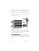
solder the Red wire of the siren to the BROWN (H1/10) wire
on the 12 pin main harness, cover the connection with electrical
tape. Ground the Black siren wire to the same location as the
BLACK (H1/8) ground wire of the 12 pin main harness.
step 10
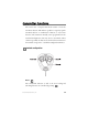
Optional connections (channel 2, 3)
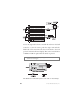
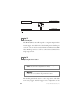
When the system receives the code controlling channel 2, for
longer than 1.5 seconds, the RED/WHITE wire (H1/12-
channel 2) will supply an output as long as the transmission
continues. This is often used to operate a trunk/hatch release or
other relay-driven function.
When the system receives the code controlling channel 3, the
output is instantaneous, and the WHITE/BLUE wire (H1/3-
channel 3) will supply an output as long as the transmission
continues. This is used to operate an accessory function.
iimmppoorrttaanntt::
Never use these wires to drive anything but a
relay or a low-current input! The transistorized output
can only supply 200 mA of current. Connecting directly
to a solenoid, motor, or other high-current device will
cause it to fail.
➜