
User`s manual


10-1
10
Appendix
10. Appendix
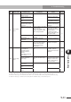
10.1 Timing chart
The following shows the timing chart from the power-on to the position command input
(when the return-to-origin is performed).
■
RDX
Control power
Main circuit power
Input
signal
Output
signal
Position command
SON
FOT
ROT
ORG
PEN
SRD
INP
RDX operation
(Note 1)
(Note 2)
(Note 2)
1000 [ms] or more
10 [ms] or more
50 [ms] or more
(Note 3)
(Note 4)
approx.10[ms]
approx.10[ms]
approx.50[ms]
Servo-offPower-off Servo-on
Return-to-origin
Servo-on
Operation
Note 1: Turn on the main circuit power after the control power has been turned on or at the same time
when the control power is turned on.
Note 2: Turn on the FOT and ROT signals 10 [ms] or more before the SON signal is turned on.
Note 3: When the return-to-origin has been completed, the INP signal turns on. So, turn off the ORG signal
after the INP signal has turned on.
Note 4: Turn on the PEN signal 10 [ms] or more before the position command is input.
position command input
■
RDP
Control power
Main circuit power
Position command
SON
FOT
ROT
(Note 3)
ORG
PEN
(Note 4)
SRD
approx.10[ms]
INP
RDP operation
Power-off
Servo-off
Magnetic pole
position estimation
Servo-on
Return-to-origin
Servo-on Operation
Note 1: Turn on the main circuit power after the control power has been turned on or at the same time
when the control power is turned on.
Note 2: Turn on the FOT and ROT signals 10 [ms] or more before the SON signal is turned on.
Note 3: When the return-to-origin has been completed, the INP signal turns on. So, turn off the ORG signal
after the INP signal has turned on.
Note 4: Turn on the PEN signal 10 [ms] or more before the position command is input.
(Note 1)
1000 [ms] or more
10 [ms] or more
(Note 2)
(Note 2)
Input
signal
Output
signal
position command input