
User`s manual


Parameter description
6
6-32
6. Parameter description
6.3.3 Reference graph for setting the acceleration and
position control cut-off frequency
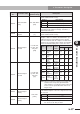
For your reference, the following graphs show payload, acceleration, and position
control cut-off frequency (Fd-09), plotted when the moment of inertia or mover mass
(Fd-00), speed control cut-off frequency (Fd-01), and speed control integral gain (Fd-03)
parameters are set to the specified values for each robot model. By referring to these
graphs, set the position control cut-off frequency (Fd-09) and acceleration that match the
required payload.
How to read graph
Example: T7-12
Model
T7-12
Maximum payload [kg] 8.0 [kg]
Fd-00 Moment of inertia 0.125 [×10
-4
kg •m
2
]
Fd-01
Speed control cut-off frequency
100.0 [Hz]
Fd-03 Speed control integral gain 65.0 [%]
0.00
0.10
0.20
0.30
0.40
0.50
0.60
0.0 1.0 2.0 3.0 4.0 5.0 6.0 7.0 8.0
0.0
2.0
4.0
6.0
8.0
10.0
12.0
14.0
Fd-09[Hz]
Acceleration
[G]
Fd-09[Hz]
Payload
[kg]
Acceleration
[G]
Payload
[kg]
Acceleration
[G
]
Fd-09
[Hz]
0.0 0.55 11.6
2.0 0.49 8.8
4.0 0.43 7.0
6.0 0.37 5.9
8.0 0.31 5.0
0.46[G]0.46[G]
7.85[Hz]
7.85[Hz]
The above table shows
examples for setting accel-
erations and position control
cut-off frequencies (Fd-09)
that match different
payloads. If the required
payload is not listed in this
table, refer to the graph on
the right.
Example: If a payload of 3kg is required,
then the acceleration is 0.46 [G]
and the position control cut-off
frequency (Fd-09) is 7.85 [Hz].