
User`s manual


6-29
6
Parameter description
6. Parameter description
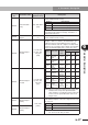
(4) Control constant parameter
Parameter
No.
Parameter name
Setting range
[Default value]
Description
Fd-00
Moment of inertia
(RDX)
"Motor rotor
inertia" to "motor
rotor inertia
×
128"
RDX (×10
-4
kg·m
2
)
RDP (×10kg)
[Depends on model]
Use this parameter to set the entire mover mass
including both rotary motor and load. This parameter
can also be set automatically by auto-tuning.
Mover mass
(RDP)
Use this parameter to set the entire mover mass
including both linear motor and load. This parameter
can also be set automatically by auto-tuning.
Fd-01
Speed control cut-
off frequency
0.1 to 500.0
(Hz)
[Depends on model]
The speed control gain for speed PI control is
calculated from the mover mass and this parameter
setting. Usually set this parameter to a value close
to the 3dB cut-off frequency obtained by measuring
the frequency characteristic with a repetitive
waveform when the speed control section performs
PI control. When IP control is specified in Fd-05, the
response speed becomes lower than the set value.
Fd-02
Speed control
proportional gain
0.01 to 300.00
(%)
[Depends on model]
Set this parameter to adjust the proportional gain
used for speed PI control. When set to 100%, the
proportional gain is set to the constant specified in
Fd-00 and Fd-01.
(Proportional gain)
∝
(Fd-00)
×
(Fd-01)
×
Fd-02 / 100
Fd-03
Speed control
integral gain
0.01 to 300.00
(%)
[Depends on model]
Set this parameter to adjust the integral gain used for
speed PI control. When set to 100%, the integral gain
is set to the constant specified in Fd-00 and Fd-01.
(Integral gain)
∝
(Fd-00)
×
(Fd-01)
2
×
Fd-03 / 100
Fd-04 P-control gain
0.1 to 99.9
(%)
[Depends on model]
Set the gain used for speed P control. Set it by the
torque (rated torque) to be output when a 1% speed
deviation is provided.
Fd-05 IP-control gain
0.00 to 1.00
[Depends on model]
Use this parameter to continuously switch the
speed feedback loop between PI and IP. When
this parameter is set to 0, ordinary PI control
is performed. At 1.00, IP control is performed.
However, if this parameter (Fd-05) is set to a
large value while Fd-00 and Fd-01 are large, then
oscillation might occur. In this case, reduce Fd-02
to avoid such oscillation.
Fd-06
Torque command
filter time constant
0.00 to 500.00
(ms)
[Depends on model]
This parameter sets the time constant for the first-order
lag filter to be applied to the torque command value.
When this parameter is set to 0, no filtering is performed.
Fd-07
Position phase
compensating
ratio
0.01 to 9.99
[Depends on model]
Sets the compensation ratio for the phase lag filter
to apply to the speed command value serving as the
position control loop output.
When this parameter exceeds 1, a phase lag occurs.
Fd-08
Position phase
compensating
time constant
0.1 to 999.9
(ms)
[Depends on model]
Sets the compensation time constant for the phase
lag filter to apply to the speed command serving as
the position control loop output.
Fd-09
Position control
cut-off frequency
0.01 to 99.99
(Hz)
[Depends on model]
Sets the response frequency of the position
feedback loop. Usually set this parameter to about
1/6 of the speed control cut-off frequency.
Fd-10
Position feed
forward gain
0.00 to 1.00
[Depends on model]
Sets the ratio used to perform feed-forward
compensation for the position control.
Fd-12
Notch filter 1
frequency
3.0 to 1000.0
(Hz)
[Depends on model]
Sets the resonance frequency of notch filter 1.
(Use TOP software to set this parameter.)
Fd-13
Notch filter 1
bandwidth
0 to 40
(dB)
[Depends on model]
Sets the bandwidth of notch filter 1 at the resonance
frequency.
(Use TOP software to set this parameter.)