
User`s manual


6-25
6
Parameter description
6. Parameter description
(3) Input/output terminal parameters
Parameter
No.
Parameter name
Setting range
[Default value]
Description
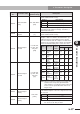
FC-01
Input terminal
polarity setting
0000 to 3FFF
[0400]
Sets the ON/OFF logic for the input terminals.
(Usually the logic is positive so the function turns on
when the external contact is closed.)
The logic setting for each terminal is assigned to
each bit of the parameter to set the logic as follows.
Bit setting
Input terminal logic
0
Positive logic: Function turns on
when the external contact is closed.
1
Negative logic: Function turns on
when the external contact is opened.
The following tables show input terminals and bit
assignment by this parameter.
bit 15 bit 14 bit 13 bit 12
O
Assigned not
O
Assigned not
CER PEN
bit 11 bit 10 bit 9 bit 8
ORG ORL
Assigned not Assigned not
bit 7 bit 6 bit 5 bit 4
Assigned not Assigned not
ROT FOT
bit 3 bit 2 bit 1 bit 0
TL
Assigned not
RS SON
FC-02
Output terminal
polarity setting
0000 to 00FF
[0002]
Sets the ON/OFF logic for the output terminals.
(Usually the logic is positive so the contact output
turns on when the output function is ON.)
The logic setting for each terminal is assigned to
each bit of the parameter to set the logic as follows.
Bit setting
Output terminal logic
0
Positive logic: The contact output turns
on when the output function is ON.
1
Negative logic: The contact output turns
off when the output function is ON.
The following tables show output terminals and bit
assignment by this parameter.
bit 15 bit 14 bit 13 bit 12
O
Assigned not
O
Assigned not
O
Assigned not
O
Assigned not
bit 11 bit 10 bit 9 bit 8
O
Assigned not
O
Assigned not
O
Assigned not
O
Assigned not
bit 7 bit 6 bit 5 bit 4
Assigned not Assigned not
BRK
Assigned not
bit 3 bit 2 bit 1 bit 0
Assigned not
INP ALM SRD