
Instruction manual


CHAPTER 3 Operating Procedures
3 - 24
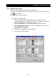
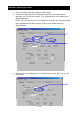
(2) Digital trace setup procedure
1- Check the channels to be validated (by entering a check mark in the
associated check boxes). Up to four channels of digital contacts can be traced.
2- From the drop-down menu, choose a trace target.
(All input / output terminal data is selectable as the candidate for trace. Refer
to [3.4 Operation Trace Function].)
3- From the drop-down menu, choose the name of the terminal to be traced.
(All input / output terminal data is selectable as the candidate for trace. Refer
to [3.4 Operation Trace Function].)
4- Specify the display color.
5- Enter a graph label name.
6- Check the channel for triggering.
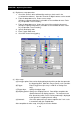
(3) Other setup
(a)Pre-trigger points:Data can be displayed beginning with a position that precedes
the triggering point. Make this entry to specify such a position.
(b)Trigger: Enter a trigger level (this entry is valid for an analog trace
only).
(c)Trigger edge: Specify the trigger edge.
(d)Sampling period: Specify the sampling intervals. Data will be sampled at the
specified intervals for display purposes. The maximum trace
time (time during which a trace can be performed) is displayed
to the right of the sampling interval setting.
(e)Automatic: Check this option when you want to optimize the Y-axis scale
in accordance with the sampled data.
After completion of entire setup, click [OK] to close the window.
1-
2-
3-
4-
5-
6-
(a)
(d)
(e)
(b)
(c)