
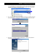
Instruction manual


CHAPTER 2 Connecting to AD Series Servo Drive
2 - 2
2. Connecting to AD Series Servo Drive
Q Wiring precautions
CAUTION
1. When disconnecting or connecting the communication cable, be sure that the servo drive
and personal computer are both turned off. If you disconnect or connect the
communication cable while the power is on, the servo drive and personal computer may
become defective.
2. While the AC Servo Drive Setup Software is running, never disconnect or connect the
communication cable. When the communication cable is reconnected, be sure to exit the
software and restart. If you do not restart the software, the software and servo drive may
malfunction.
Q Usage precautions
CAUTION
1. When the servo drive control power is turned off, be sure to exit the AC Servo Drive Setup
Software and restart. If you turn on the servo drive control power without exiting the
software, the software and servo drive may malfunction.
2. Do not turn off the servo drive control power while the initialization or parameter rewrite
process is in progress. If the servo drive control power turns off during a write, the
EEPROM data in the servo drive may become damaged, causing the servo drive to
improperly operate.
This section explains about the connection between the AD Series Servo Drive and PC.
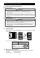
2.1 Connection Cable
Create a cable that is wired as indicated below, or purchase the product suggested below:
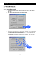
Wiring diagram
The communication cable between the drive and PC
2.2 Connecting to the Servo Drive
With the above-mentioned cable, connect the servo drive to the personal computer.
Servo drive : Connector marked "PC"
Personal computer : RS-232C connector
8 GND
7 —
6 —
5 ER2
4 SD
3 RD
2 DR
1 RS
1 DCD
2 R x D
3 T x D
4 DTR
5 GND
6 DSR
7 RTS
8 CTS
9 —
8-pin modular connector
D-SUB 9-pin connecto
r
1
8
8-pin
Drive PC
Model Name
ADCH-AT2 The communication cable
between the drive and PC
drive PC
8-pin modular connector D-SUB 9-pin connector