Hitachi AC Servo Drive AD Series Setup Software AHF-P01/P02 Instruction Manual Thank you for purchasing Hitachi AC Servo Drive Setup Software. This instruction manual describes all the functions of Hitachi AC Servo AD Series Setup Software AHF-P01 and furnishes the common usage instructions for AHF-P01 and AHF-P02, excluding AHF-P02's program editor functions. For proper software installation and use, thoroughly read this instruction manual before using the software.
Q IMPORTANT Keep this instruction manual at a place near the software operating personnel. Before installing, running, or otherwise using the software, be sure to thoroughly read this instruction manual. Use the software properly in accordance with the knowledge of the machine, safety instructions, precautions, operating instructions, and other handling procedures. Always use the software without exceeding the specified limits stated in this instruction manual.
SAFETY PRECAUTIONS The AC Servo Drive Setup Software is used to connect the Hitachi AC Servo Drive AD Series to a personal computer. It does not operate independently. When operating a servo drive, thoroughly read its instruction manual as well as this instruction manual for safety assurance. The safety precautions set forth in this instruction manual are classified into the WARNING and CAUTION categories.
MEMO
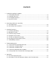
CONTENTS 1. Installing/Uninstalling the Software 1.1 Preinstallation Checkout....................................................................................................... 1-2 1.2 Installation Procedure ........................................................................................................... 1-2 1.3 Uninstallation Procedure ...................................................................................................... 1-8 1.4 Upgrade Procedure .............................
MEMO
CHAPTER 1 Installing/Uninstalling the Software This section describes the preinstallation checkout procedure, installation procedure, uninstallation procedure, and upgrade procedure for the AC Servo Drive Setup Software. 1. Installing/Uninstalling the Software 1.1 Preinstallation Checkout ......................................... 1-2 1.2 Installation Procedure ............................................. 1-3 1.3 Uninstallation Procedure ......................................... 1-8 1.
CHAPTER 1 Installing/Uninstalling the Software 1. Installing/Uninstalling the Software The install program (SETUP.EXE) supplied on a product disk creates a new directory on a specified hard disk and copies files to install the software. 1.1 Preinstallation Checkout Before installing the software, complete the following checks: 1- Space check Before installing the software, check that the installation destination hard disk has at least 30MB of free space.
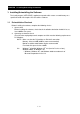
CHAPTER 1 Installing/Uninstalling the Software 1.2 Installation Procedure The following instructions presume that you install the software onto hard disk drive C from floppy disk drive A. 1- Start Windows 95/98 or Windows NT, Windows 2000, or Windows XP. 2- Exit unnecessary resident programs. (If you do not observe this precaution, the installation process may become unstable or fail.) 3- From the menu on the taskbar, choose [Settings] and then click [Control Panel ].
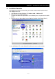
CHAPTER 1 Installing/Uninstalling the Software 4- Click the [Add/Remove Programs] icon to open the following window: In case of Windows XP, click the [Add or Remove Programs] icon. OS: In case of Windows 98 OS: In case of Windows NT OS: In case of Windows XP 5- 6- From the window shown above, click the [Install ] button. In case of Windows XP, click the [Add New Programs] icon and then click the [CD or Floppy] icon.
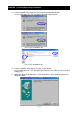
CHAPTER 1 Installing/Uninstalling the Software 7- After the product disk is inserted into the floppy disk drive, click the [Next ] button. When the following window opens, verify the selected drive and then click the [Finish] button. If a wrong drive is selected, click the [Browse] button to select the "setup.exe" file on Setup Disk 1. 8- When the install program starts as indicated below, select the language to install and click the [OK] button.
CHAPTER 1 Installing/Uninstalling the Software 10- Select an installation destination folder. To select a folder other than the default one, click the [Browse] button to specify the installation destination folder. After completion of folder selection, click the [Next ] button. 11- Select the product you want to install. For the standard software (AHF-P01), do nothing but click the [Next ] button.
CHAPTER 1 Installing/Uninstalling the Software 12- The file copy process then starts. 13- When the files on the first product disk are completely copied, the following dialog box opens. Insert Setup Disk 2 into the floppy disk drive and then click the [OK] button to resume the file copy process. Repeat this procedure for the remaining disks (Setup Disks 3,4 and 5). NOTE) All the setup disks may not always be used for a reinstall.
CHAPTER 1 Installing/Uninstalling the Software 15- The system needs to be updated and restarted. When the following window opens, close all the other open applications, choose "Yes, I want to restart my computer now", remove the product disk from the floppy disk drive, and click the [Finish] button to restart the system. 1.3 Uninstallation Procedure You can uninstall the software by performing the following steps: 1- From the menu on the taskbar, choose [Settings] and then click [Control Panel].
CHAPTER 1 Installing/Uninstalling the Software In case of Windows XP, to remove AHF from your PC, choose [Control Panel] from the menu on the taskbar, click the [Add or Remove Programs] icon, choose [AHF] and then click the [Change or Remove Programs]. 2- The same program then starts as for installation and displays the following dialog box. Click the [OK] button in the dialog box. The AHF uninstallation process then starts. 3- When AHF is uninstalled, the following window opens.
CHAPTER 1 Installing/Uninstalling the Software 1.4 Upgrade Procedure To upgrade the software, first uninstall the existing version of Setup Software AHF in a manner explained earlier and then install the new version.
CHAPTER 2 Connecting to AD Series Servo Drive This section describes the cable for connecting the personal computer to the AD Series Servo Drive and explains how to make the connection. 2. Connecting to AD Series Servo Drive 2.1 Connection Cable.................................................... 2-2 2.2 Connecting to the Servo Drive ................................
CHAPTER 2 Connecting to AD Series Servo Drive 2. Connecting to AD Series Servo Drive Q Wiring precautions CAUTION 1. When disconnecting or connecting the communication cable, be sure that the servo drive and personal computer are both turned off. If you disconnect or connect the communication cable while the power is on, the servo drive and personal computer may become defective. 2. While the AC Servo Drive Setup Software is running, never disconnect or connect the communication cable.
CHAPTER 3 Operating Procedures This section describes the procedures for launching and exiting the AC Servo Drive Setup Software, exercising its monitoring, parameter setup, operation trace, and test run functions, and changing the communication format. 3. Operating Procedures 3.1 Launching and Exiting............................................. 3-2 3.2 Monitoring Function................................................. 3-4 3.3 Parameter Setup Function ...................................... 3-6 3.
CHAPTER 3 Operating Procedures 3. Operating Procedures 3.1 3.1.1 Launching and Exiting Launching the software 12- From the menu on the task bar, choose [Programs (P)], point to [Ahf], and then click [Ahf]. The software then starts and opens the following window: Connection button 3- To connect to the servo drive, click the [Connect (C)] button. When the connection is established normally, the following window opens in several seconds, offering you an increased number of selectable buttons.
CHAPTER 3 Operating Procedures 3.1.2 Exiting the software (1) In the case of exiting AHF 1- Close all open windows except the opening window. Exit 2- In the opening window, click the [Exit (E)] button. (2) In the case of exiting only connection 1- Close all open windows except the opening window. Disconnect 2- In the opening window, click the [Disconnect (X)] button.
CHAPTER 3 Operating Procedures 3.2 Monitoring Function You can use the monitoring function to view the operation information in real time. 3.2.1 Starting the monitoring function In the opening window, click the [Monitor Display(M)] button.
CHAPTER 3 Operating Procedures 3.2.2 Description of the monitoring function window The figure below describes the monitoring function: Displays the operation information in real time. Furnishes the information about operation by indicating that the servo drive is stopped, being operated, cannot be driven, cannot be driven forward, or cannot be driven backward. Displays the input terminal status in real time (0: OFF; 1: ON). Shows the current operation control mode.
CHAPTER 3 Operating Procedures 3.3 Parameter Setup Function You can use the parameter setup function to set and manage the servo drive parameters. 3.3.1 Starting the parameter setup function In the opening window, click the [Parameter setting (S)] button.
CHAPTER 3 Operating Procedures 3.3.2 Description of the parameter setup window The contents of the parameter setup window are shown below: Open Save As Print Read Write Default You can assign a title. (The title is displayed at the time of printing.) Parameter group setup tab Specify the parameter group you want to set up. To apply parameter changes, edit the data in this column. When you edit data, it appears in red and becomes suffixed with an asterisk (*).
CHAPTER 3 Operating Procedures 3.3.3 Editing the parameters Two examples are presented in this section to explain about the parameter editing procedure. • Choosing from a drop list --- Example 1) Editing FA-00 • Inputting value directly --- Example 2) Editing Fb-00 (Example 1) Editing FA-00 1- Choose the FA tab, click the mouse on the FA-00 setting field, and select a new setting from the drop-down menu. Note 1) (0) showed after S-P means the value used in the servo drive internally.
CHAPTER 3 Operating Procedures 3- Choose [Parameter (P)] on the menu bar and then choose [Write (W)], or click the mouse on on the toolbar. 4- When the following dialog box opens, choose [OK]. 5- The following message then appears to indicate that a parameter write is in progress. 6- In case of finishing rewriting parameters, red value becomes black and symbol “*” attached to the right side of the value is disappeared.
CHAPTER 3 Operating Procedures (Example 2) Editing Fb-00 1- Choose the Fb tab, click the mouse on the Fb-00 setting field, and enter a new setting. For choosing Fb Note 1) An error occurs on the screen when an attempt is made to rewrite writeprotected parameters while an operation is performed with the SON terminal turned on. Note 2) An error occurs on the screen when an attempt is made to write parameter data that is outside the acceptable parameter range.
CHAPTER 3 Operating Procedures 5- The following message then appears to indicate that a parameter write is in progress. 6- In case of finishing rewriting parameters, red value becomes black and symbol “*” attached to the right side of the value is disappeared.
CHAPTER 3 Operating Procedures This parameter can not be changed. NOTE 3: You cannot edit the parameters displayed in the parameter setup window if the red "???" mark is displayed to the right of their settings. NOTE 4: Do not turn off the servo drive control power while a parameter write is in progress. If it turns off during a parameter write, the EEPROM data in the servo drive may become damaged, causing the servo drive to improperly operate.
CHAPTER 3 Operating Procedures 3.3.4 Saving the parameters You can save the parameters in a file for parameter management purposes. 1- In the parameter setup window, choose [File (F)] on the menu bar and then choose [Save As (S)], or click the mouse on 2- on the toolbar. When the Save As window opens, specify the file name and save destination. You can save the file in either of the following two different formats: CSV: Saves the file in a comma-separated value form.
CHAPTER 3 Operating Procedures 3.3.5 Loading the parameters A file saved in a manner described in the preceding section can be used to set up the parameters. 1- In the parameter setup window, choose [File (F)] on the menu bar and then choose [Open (O)], or click the mouse on on the toolbar. 2- When the Open window opens, specify the name of the file to load and its storage location. Note, however, that only CSV files can be loaded.
CHAPTER 3 Operating Procedures 3.3.6 Reverting to factory default You can revert to the factory default parameter settings. You can use this feature if, for instance, the parameters are improperly set due to an operating error. This operation can be done by pull-down menu. 1- In the parameter setup window, choose [Parameter (P)] on the menu bar and then on the toolbar.
CHAPTER 3 Operating Procedures 3.3.7 Printing the parameters You can print out parameter data to compile a report. 1- In the parameter setup window, choose [File (F)] on the menu bar and then choose [Print (P)], or click the mouse on 2- 3.3.8 on the toolbar. When the printer setup window opens, enter appropriate setup data to print out the parameters.
CHAPTER 3 Operating Procedures 3.4 Operation Trace Function This function enables you to visually confirm the servo drive operation. The table below shows the traceable items and control states.
CHAPTER 3 Operating Procedures 3.4.1 Starting the operation trace function The operation trace window opens when you click the [Trace operation (D)] button in the opening window.
CHAPTER 3 Operating Procedures 3.4.2 Description of the operation trace window The figure below describes the contents of the operation trace window: Open Time display based on t1axis cursor Save As Print Start Operation Trace Clear Graph You can assign a title. (The title is displayed at the time of printing.
CHAPTER 3 Operating Procedures 3.4.3 Operation trace sequence 1- Open the operation trace window. 2- Perform trace setup (see the next page for the setup procedure). To do this, choose [Trace operation (T)] on the menu bar and then choose [Trace setting (O)], or click on the toolbar. After completion of trace setup, click [OK].
CHAPTER 3 Operating Procedures 3- Start an operation trace. To do this, choose [Trace operation (T)] on the menu bar and then choose [Trace Start (S)], or click on the toolbar. When an operation trace starts, the above message appears. 4- When you click the trigger condition button or [Manual trigger] button in the above dialog box, the servo drive transfers data to the personal computer and the following dialog box opens.
CHAPTER 3 Operating Procedures 5- Upon completion of data transfer, the data appears as shown below.
CHAPTER 3 Operating Procedures 3.4.4 Operation trace setup The trace setup window can be opened as directed below: Choose [Trace operation (T)] on the menu bar and then choose [Trace setting (O)], or click on the toolbar. After completion of setup, click [OK]. (1) Analog trace setup procedure 1- Check the channels to be validated (by entering a check mark in the associated check boxes). Up to four channels of analog data can be traced. 2- From the drop-down menu, choose a trace target. Refer to [3.
CHAPTER 3 Operating Procedures (2) Digital trace setup procedure 1- Check the channels to be validated (by entering a check mark in the associated check boxes). Up to four channels of digital contacts can be traced. 2- From the drop-down menu, choose a trace target. (All input / output terminal data is selectable as the candidate for trace. Refer to [3.4 Operation Trace Function].) 3- From the drop-down menu, choose the name of the terminal to be traced.
CHAPTER 3 Operating Procedures 3.4.5 Graph display setup (1) X-axis setup procedure With the toolbar near a graph axis, you can enlarge the X-axis or revert to the standard size of each graph axis. Use the following toolbar buttons. X-axis one-step enlargement X-axis one-step reduction (2) Y-axis setup procedure With the toolbar near a graph axis, you can change the Y-axis scale. To change the Y-axis scale, click the following toolbar button. Y-axis scaling change The following window then opens.
CHAPTER 3 Operating Procedures (3) Hiding a graphed line You can hide a graphed line by removing the associated check mark as indicated below. To redisplay the graphed line, put a check mark back in the check box. For hiding or displaying a graphed line (4) Clearing the contents of the window You can erase the on-screen graph by choosing [Trace operation (T)] on the menu bar and then choosing [Clear display (C)], or click on the toolbar.
CHAPTER 3 Operating Procedures 3.5 Test Run and Adjustment Functions This section describes the functions that are useful for a test run. 3.5.1 Jogging and homing With the personal computer, you can start a jog operation or return the servomotor to its home for test run purposes. The jog operation function can be exercised to check the servo drive, servomotor, power supply, or other wiring. (For the use of the jog operation function, no external I/O wiring connection is necessary.
CHAPTER 3 Operating Procedures 23- Enter the speed command for jogging in field 2 below. Conform the safety and then click a button to specify the desired direction of operation (see 3) in the figure below). (The servomotor then starts rotating in the specified direction.) NOTE: Since this step causes the servomotor to run, confirm the safety beforehand. Upon completion of the above step, the contents of the window change as indicated below.
CHAPTER 3 Operating Procedures (1-B) Pulse feed jog operation procedure In compliance with a given position command, the pulse feed jogging operation is performed in the position control mode until the specified position is reached. NOTE 1: While this operation is being conducted, do not enter a signal from the SON terminal or other I/O connector. If such a signal enters, the operation is performed in compliance with it.
CHAPTER 3 Operating Procedures While positioning is in progress after completion of the above step, the window looks like the figure below: 3- To abort the positioning process (servo OFF), click the [Stop] button, which is numbered 3- in the above figure. 4- Upon completion of positioning, you are returned to the initial window. In the resulting state, the servo ON state continues. Therefore, click the [Stop] button, which is numbered 3- in the above figure.
CHAPTER 3 Operating Procedures 3.5.2 Off-line tuning The total inertia, including the motor inertia, can be approximately calculated in the offline state. To exercise this function, perform either of the following procedures. (1) Procedure for fully-automatic off-line tuning 1- In the opening window, click the [Test Run and Adjustment (T)] button. The following window then opens (click the Offline tuning tab).
CHAPTER 3 Operating Procedures (A) (B) (C) (D) 2- Enter the following parameters which are required for tuning: (A) Speed control cut-off frequency Set the speed control cut-off frequency for off-line tuning. Enter a setting at which no hunting occurs. (B) Tuning inertia initial value Set the inertia for the beginning of off-line tuning. When an approximate inertia value is known, make this entry to ensure that tuning is rapidly completed.
CHAPTER 3 Operating Procedures 5- After completion of inertia estimation, the operating waveform for the last pattern operation is downloaded from the servo drive to display the estimation result as indicated below: 6- After completion of tuning, be sure to finish the Auto-tuning mode by tuning SON terminal off, RS terminal on and RS terminal off. NOTE 1: Exercising this function automatically rewrites inertia setting Fd-00.
CHAPTER 3 Operating Procedures (2) Procedure for performing an off-line tuning process while verifying individual steps 12- In the opening window, click the [Test Run and Adjustment (T)] button. The following window then opens (click the Offline tuning tab). Enter the following parameters which are required for tuning: (A) Speed control cut-off frequency Set the speed control cut-off frequency for off-line tuning. Enter a setting at which no hunting occurs.
CHAPTER 3 Operating Procedures 5- After completion of inertia estimation, the operating waveform for the last pattern operation is downloaded from the servo drive to display the estimation result as indicated below: 6- Check whether the waveform is adequate. If necessary, you can click the [1 pattern tuning start] button again. A one-pattern operation is then performed to estimate the inertia. You can continue to perform tuning in this manner while checking the on-screen waveform each time.
CHAPTER 3 Operating Procedures 3.5.3 Mechanical system diagnostic measurement procedure The resonance point of the machine connected to the servomotor can be measured. The procedure is described below. NOTE: This function is for servo drive AD2 only. It does not properly work for models earlier than AD2. 1- Make preparations as directed below: Before making measurements, exercise the parameter setup function to set the parameters as shown in the following table: Parameter name 2- No.
CHAPTER 3 Operating Procedures For AD1, click [OK] and close the Machine Diagnosis window. (AD1 series is showed as “AD series”.) For AD2, click [OK] and proceed to perform the next step.
CHAPTER 3 Operating Procedures (1) Overall setup Read the following instructions. If you are sure that your machine will remain intact and create no safety hazard, you can use the default settings for making measurements. (a) Frequency range Define the machine resonance frequency measurement range as directed below: If an approximate resonance frequency is known: Enter a frequency range that covers about fives times the approximate resonance frequency.
CHAPTER 3 Operating Procedures (e) Number (of data) You can specify the number of FFT computation points for mechanical system diagnostics. The larger the number of points, the higher the measurement accuracy. However, the time required for a data upload will increase with an increase in the number of points. You can use a relatively low setting for making initial rough measurements and raise the setting for final detailed measurements to reduce the required measurement time.
CHAPTER 3 Operating Procedures 5- Turn on the servo ON(SON) signal. The servomotor then starts rotating. In an emergency, turn off the servo ON signal. 6- When the operation ends, a data upload begins.
CHAPTER 3 Operating Procedures 7- The mechanical system diagnostics window opens. 8- Turn off the servo ON signal, turn the RS terminal on and then back off, and exit the mechanical system diagnostics mode. 9- Observe the waveform to determine whether or not to make measurements again. When the resonance point is properly measured: Proceed as directed below. The waveform shown in Step 7- indicates that a relatively clear resonance point is measured.
CHAPTER 3 Operating Procedures NOTE: You might not be able to obtain a clean measurement result shown above depending on your machine no matter how many times you edit the settings. However, there is no practical problem as far as the resonance point (a peak similar to the pointed summit of a mountain) is measured.
CHAPTER 3 Operating Procedures 3.5.4 Notch filter setup procedure The notch filter parameter can be set by performing the procedure described below (it is necessary to measure the resonance point as directed in the preceding section): 1- As shown below, left-click the mouse on a resonance point (a peak similar to the pointed summit of a mountain) within the waveform display area of the mechanical diagnostics window.
CHAPTER 3 Operating Procedures 3- Click the [Filter 1] button. The recommended settings are then displayed in the boxes to the right of the clicked button. 4- You can set up to two resonance frequencies. If there is another resonance point, repeat Steps 1- and beyond and set it with the [Filter 2] button. NOTE: If resonance points are close to each other, the servomotor operation may become unstable even when you properly complete filter setup. In such an instance, set a predominant resonance point.
CHAPTER 3 Operating Procedures 3.6 Changing the Communication Format 1- In the opening window, click the [Communication format (F)] button. Communication Format 2- When the following window opens, make necessary changes: 3- After necessary changes are made, click either of the following buttons depending on the situation: When the connection is established: [Setting] button --- Changes the settings for both the servo drive and personal computer and establishes the connection again.
CHAPTER 3 Operating Procedures 3.7 1- Setting Motor parameters In the opening window, click the [Motor constants setting (I)] button. When the following window opens, set up motor constants according to the following points. Motor constants 2- Select the motor type from the pull-down button. Note that unmatched motor constants against the amplifier you use can not be set in the amplifier.
CHAPTER 3 Operating Procedures 3- Click the [Write Motor constants] button. It normally performs in order of “Check the output rating”, “Write Motor constants” and “Check Motor constants”. Which operation is performed is selectable by the check-box. Click this button to start operation. 4- When the setting is finished correctly, the following message is showed. After that [Servo amplifier initialization] button is valid.
CHAPTER 3 Operating Procedures 5- Click the [Servo amplifier initialization] button. As the following message is showed, click one of buttons [OK] button : starts to initialize parameters in the servo amplifier. [Cancel] button : cancels the initialization of parameters in the servo amplifier. 6- During the initialization, the following screens are displayed in order according to the status of process. 7- When the initialization is finished, the following message is showed.
CHAPTER 3 Operating Procedures In case that unmatched motor constants against the amplifier is selected : the error occurs at the step of “Check the output rating”. And then the following message is showed. Be sure to check the voltage class and output rating of amplifier and motor, and then select the correct motor constants.
CHAPTER 3 Operating Procedures MEMO 3 - 50
CHAPTER 4 Troubleshooting Guide This section furnishes the instructions for troubleshooting the product when it malfunctions or erratically operates. 4. Troubleshooting Guide 4.1 If the Servo Drive Cannot Be Connected ................4-2 4.2 If Parameters Cannot Be Written ............................4-2 4.3 If Parameters Cannot Be Read...............................4-2 4.4 If Parameter Initialization Does Not Work ...............4-3 4.5 If the Operation Trace Function Does Not Properly Work ..............
CHAPTER 4 Troubleshooting Guide 4. Troubleshooting Guide 4.1 If the Servo Drive Cannot Be Connected If the servo drive cannot be connected, proceed as directed below. Probable cause 4.2 Remedy A wrong connector is used for connecting the servo drive to the personal computer. Check the connector and use a correct connector. The connection cable is improperly connected or in poor contact. Check to ensure that the cable is properly connected and in proper contact.
CHAPTER 4 Troubleshooting Guide 4.4 If Parameter Initialization Does Not Work If the parameter initialization does not be work, proceed as directed below: Probable cause Remedy Parameters can not be read from the servo drive after initialization. Confirm that the indication of the initialization is displayed on the digital operator built in the servo drive. Initialize the parameters again.
CHAPTER 4 Troubleshooting Guide MEMO 4-4
CHAPTER 5 Appendixes 5. Appendixes 5.1 Files to Be Copied to System..................................5-2 5.2 Connection to a Personal Computer without a Serial Port (RS-232C)..............................
CHAPTER 5 Appendixes 5. Appendixes 5.1 Files to Be Copied to System The table below lists the names of the files that are copied to the c:\windows\system directory when you install the software (it is presumed that Windows is installed on drive C.): OCX files COMDLG32.OCX MSCOMCT2.OCX MSCOMCTL.OCX TABCTL32.OCX PDQCOM32.OCX MSFLXGRD.OCX VSVIEW3.OCX VSFLEX6D.OCX ACSGRAPH.OCX DLL files MSVBVM60.DLL OLEAUT32.DLL ASYCFILT.DLL CMDLGJP.DLL COMCAT.DLL MSCC2JP.DLL MSCMCJP.DLL OLEPRO32.DLL TABCTJP.DLL VB6JP.
CHAPTER 5 Appendixes 5.2 Connection to a Personal Computer without a Serial Port (RS-232C) When using the AC Servo Drive Setup Software on a personal computer without an RS232C port to establish a connection to the AD Series, it is suggested that you use the following PC card. If you use the following PC card, you do so at your own risk.
CHAPTER 5 Appendixes 5.2.1 Connection procedures and precautions (1) Installing the PC card Install the PC card as directed in its documentation. Note what COM port the PC card RS-232C is assigned to in the installation process. (2) Connecting Setup Software AHF When you install and launch Setup Software AHF, COM1 is set up as the communication port.
CHAPTER 5 Appendixes 5- Although the following dialog box opens, click the [OK] button. 6- Click the [Close] button. 7- Connect the PC card RS-232C cable to the servo drive connection cable. Click the [Connect] button to establish the connection. If the connection is not properly established, check the COM port assigned to the PC card and the communication baud rate, data bit, stop bit, and parity settings for the servo drive.
CHAPTER 5 Appendixes MEMO 5-6