
Data Sheet

Compute Module Datasheet
Copyright Raspberry Pi (Trading) Ltd. 2016
9 Peripherals
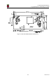
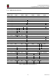
9.1 GPIO
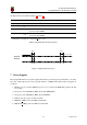
BCM283x has in total 54 GPIO lines in 3 separate voltage banks. All GPIO pins have at least two
alternative functions within the SoC. When not used for the alternate peripheral function, each GPIO
pin may be set as an input (optionally as an interrupt) or an output. The alternate functions are usually
peripheral I/Os, and most peripherals appear twice to allow flexibility on the choice of I/O voltage.
On CM1, CM3 and CM3L bank2 is used on the module to connect to the eMMC device and, on CM3
and CM3L, for an on-board I2C bus (to talk to the core SMPS and control the special function pins). On
CM3L most of bank 2 is exposed to allow a user to connect their choice of SD card or eMMC device (if
required).
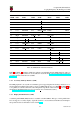
Bank0 and 1 GPIOs are available for general use. GPIO0 to GPIO27 are bank 0 and GPIO28-45 make
up bank1. GPIO0-27 VDD is the power supply for bank0 and GPIO28-45 VDD is the power supply for
bank1. SDX VDD is the supply for bank2 on CM3L. These supplies can be in the range 1.8V-3.3V (see
Table 7) and are not optional; each bank must be powered, even when none of the GPIOs for that bank
are used.
Note that the HDMI HPD N 1V8 and EMMC EN N 1V8 pins (on CM1 these were called GPIO46 1V8
and GPIO47 1V8 respectively) are 1.8V IO and are used for special functions (HDMI hot plug de-
tect and boot control respectively). Please do not use these pins for any other purpose, as the
software for the Compute Module will always expect these pins to have these special functions. If
they are unused please leave them unconnected.
All GPIOs except GPIO28, 29, 44 and 45 have weak in-pad pull-ups or pull-downs enabled when the
device is powered on. It is recommended to add off-chip pulls to GPIO28, 29, 44 and 45 to make sure
they never float during power on and initial boot.
17 Version 1.0