
Datasheet

Compute Module Datasheet
Copyright Raspberry Pi (Trading) Ltd. 2016
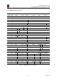
Supply Minimum Requirement Unit
VBAT (CM1) 2000
a
mW
VBAT (CM3,3L) 3500
a
mW
3V3 250 mA
1V8 250 mA
VDAC 25 mA
GPIO0-27 VDD 50
b
mA
GPIO28-45 VDD 50
b
mA
SDX VDD 50
b
mA
a
Recommended minimum. Actual power drawn is very dependent on use-case
b
Each GPIO can supply up to 16mA, aggregate current per bank must not exceed 50mA
Table 8: Mimimum Power Supply Requirements
8 Booting
The 4GB eMMC Flash device on CM3 is directly connected to the primary BCM2837 SD/eMMC inter-
face. These connections are not accessible on the module pins. On CM3L this SD interface is available
on the SDX pins.
When initially powered on, or after the RUN pin has been held low and then released, the BCM2837
will try to access the primary SD/eMMC interface. It will then look for a file called bootcode.bin on the
primary partition (which must be FAT) to start booting the system. If it cannot access the SD/eMMC
device or the boot code cannot be found, it will fall back to waiting for boot code to be written to it over
USB; in other words, its USB port is in slave mode waiting to accept boot code from a suitable host.
A USB boot tool is available on Github which allows a host PC running Linux to write the BCM2837
boot code over USB to the module. That boot code then runs and provides access to the SD/eMMC as a
USB mass storage device, which can then be read and written using the host PC. Note that a Raspberry Pi
can be used as the host machine. For those using Windows a precompiled and packeged tool is available.
For more information see here.
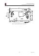
The Compute Module has a pin called EMMC DISABLE N which when shorted to GND will disable
the SD/eMMC interface (by physically disconnecting the SD CMD pin), forcing BCM2837 to boot from
USB. Note that when the eMMC is disabled in this way, it takes a couple of seconds from powering up
for the processor to stop attempting to talk to the SD/eMMC device and fall back to booting from USB.
Note that once booted over USB, BCM2837 needs to re-enable the SD/eMMC device (by releasing
EMMC DISABLE N) to allow access to it as mass storage. It expects to be able to do this by driving
the EMMC EN N 1V8 pin LOW, which at boot is initially an input with a pull up to 1V8. If an end user
wishes to add the ability to access the SD/eMMC over USB in their product, similar circuitry to that
used on the Compute Module IO Board to enable/disable the USB boot and SD/eMMC must be used;
that is, EMMC DISABLE N pulled low via MOSFET(s) and released again by MOSFET, with the gate
controlled by EMMC EN N 1V8. Ensure you use MOSFETs suitable for switching at 1.8V (i.e. use a
device with gate threshold voltage, Vt, suitable for 1.8V switching).
16 Version 1.0