
Datasheet

06 February 2012 Broadcom Europe Ltd. 406 Science Park Milton Road Cambridge CB4 0WW Page 97
© 2012 Broadcom Corporation. All rights reserved
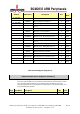
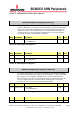
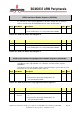
Bit(s) Field Name Description Type Reset
31-22 -
Reserved
R 0
21-0 EDSn
(n=32..53)
0 = Event not detected on GPIO pin n
1 = Event detected on GPIO pin n
R/W 0
Table 6-15 – GPIO Event Detect Status Register 1
GPIO Rising Edge Detect Enable Registers (GPRENn)
S
YNOPSIS
The rising edge detect enable registers define the pins for which a rising edge
transition sets a bit in the event detect status registers (GPEDSn). When the
relevant bits are set in both the GPRENn and GPFENn registers, any transition (1
to 0 and 0 to 1) will set a bit in the GPEDSn registers. The GPRENn registers use
synchronous edge detection. This means the input signal is sampled using the
system clock and then it is looking for a “011” pattern on the sampled signal. This
has the effect of suppressing glitches.
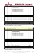
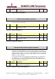
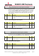
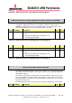
Bit(s) Field Name Description Type Reset
31-0 RENn (n=0..31)
0 = Rising edge detect disabled on GPIO pin
n.
1 = Rising edge on GPIO pin n sets corresponding bit
in EDSn.
R/W 0
Table 6-16 – GPIO Rising Edge Detect Status Register 0
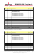
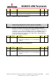
Bit(s) Field Name Description Type Reset
31-22 -
Reserved
R 0
21-0 RENn
(n=32..53)
0 = Rising edge detect disabled on GPIO pin
n.
1 = Rising edge on GPIO pin n sets corresponding bit
in EDSn.
R/W 0
Table 6-17 – GPIO Rising Edge Detect Status Register 1