
Datasheet

06 February 2012 Broadcom Europe Ltd. 406 Science Park Milton Road Cambridge CB4 0WW Page 90
© 2012 Broadcom Corporation. All rights reserved
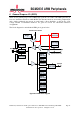
The GPIO peripheral has three dedicated interrupt lines. These lines are triggered by the
setting of bits in the event detect status register. Each bank has its’ own interrupt line with the
third line shared between all bits.
The Alternate function table also has the pull state (pull-up/pull-down) which is applied after
a power down.
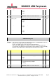
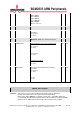
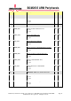
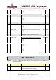
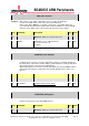
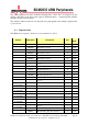
6.1 Register View
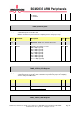
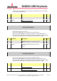
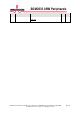
The GPIO has 41 registers. All accesses are assumed to be 32-bit.
Address Field Name Description Size
Read/
Write
0x 7E20 0000
GPFSEL0
GPIO Function Select 0
32 R/W
0x 7E20 0000
GPFSEL0
GPIO Function Select 0
32 R/W
0x 7E20 0004
GPFSEL1
GPIO Function Select 1
32 R/W
0x 7E20 0008
GPFSEL2
GPIO Function Select 2
32 R/W
0x 7E20 000C
GPFSEL3
GPIO Function Select 3
32 R/W
0x 7E20 0010
GPFSEL4 GPIO Function Select 4
32 R/W
0x 7E20 0014
GPFSEL5 GPIO Function Select 5
32 R/W
0x 7E20 0018
- Reserved
- -
0x 7E20 001C
GPSET0 GPIO Pin Output Set 0 32 W
0x 7E20 0020
GPSET1 GPIO Pin Output Set 1 32 W
0x 7E20 0024
- Reserved - -
0x 7E20 0028
GPCLR0 GPIO Pin Output Clear 0 32 W
0x 7E20 002C
GPCLR1 GPIO Pin Output Clear 1 32 W
0x 7E20 0030
- Reserved - -
0x 7E20 0034
GPLEV0 GPIO Pin Level 0 32 R
0x 7E20 0038
GPLEV1 GPIO Pin Level 1 32 R
0x 7E20 003C
- Reserved - -
0x 7E20 0040
GPEDS0 GPIO Pin Event Detect Status 0 32 R/W
0x 7E20 0044
GPEDS1 GPIO Pin Event Detect Status 1 32 R/W
0x 7E20 0048
- Reserved - -
0x 7E20 004C
GPREN0 GPIO Pin Rising Edge Detect Enable 0 32 R/W
0x 7E20 0050
GPREN1 GPIO Pin Rising Edge Detect Enable 1 32 R/W
0x 7E20 0054
- Reserved - -
0x 7E20 0058
GPFEN0 GPIO Pin Falling Edge Detect Enable 0 32 R/W
0x 7E20 005C
GPFEN1 GPIO Pin Falling Edge Detect Enable 1 32 R/W