
Datasheet

06 February 2012 Broadcom Europe Ltd. 406 Science Park Milton Road Cambridge CB4 0WW Page 47
© 2012 Broadcom Corporation. All rights reserved
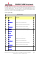
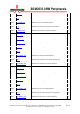
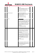
0xe04
14_CONBLK_AD
DMA Channel 14 Control Block Address
32
0xe08
14_TI
DMA Channel 14 CB Word 0 (Transfer Information)
32
0xe0c
14_SOURCE_AD
DMA Channel 14 CB Word 1 (Source Address)
32
0xe10
14_DEST_AD
DMA Channel 14 CB Word 2 (Destination Address)
32
0xe14
14_TXFR_LEN
DMA Channel 14 CB Word 3 (Transfer Length)
32
0xe1c
14_NEXTCONBK
DMA Channel 14 CB Word 5 (Next CB Address)
32
0xe20
14_DEBUG
DMA Channel 14 Debug
32
0xfe0
INT_STATUS
Interrupt status of each DMA channel
32
0xff0
ENABLE
Global enable bits for each DMA channel
32
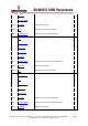
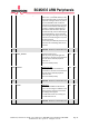
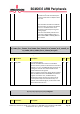
0_CS 1_CS 2_CS 3_CS 4_CS 5_CS 6_CS 7_CS 8_CS 9_CS 10_CS 11_CS 12_CS 13_CS 14_CS Register
Synopsis
DMA Control And Status register contains the main control and status bits for this DMA channel.
Bit(s)
Field Name
Description
Type
Reset
31
RESET
DMA Channel Reset
Writing a 1 to this bit will reset the DMA.
The bit cannot be read, and will self
clear.
W1SC
0x0
30
ABORT
Abort DMA
Writing a 1 to this bit will abort the
current DMA CB. The DMA will load the
next CB and attempt to continue. The bit
cannot be read, and will self clear.
W1SC
0x0
29
DISDEBUG
Disable debug pause
signal
When set to 1, the DMA will not stop
when the debug pause signal is asserted.
RW
0x0