
Datasheet

06 February 2012 Broadcom Europe Ltd. 406 Science Park Milton Road Cambridge CB4 0WW Page 36
© 2012 Broadcom Corporation. All rights reserved
3.3 10 Bit Addressing
10 Bit addressing is an extension to the standard 7-bit addressing mode. This section
describes in detail how to read/write using 10-bit addressing with this I2C controller.
10-bit addressing is compatible with, and can be combined with, 7 bit addressing. Using 10
bits for addressing exploits the reserved combination 1111 0xx for the first byte following a
START (S) or REPEATED START (Sr) condition.
The 10 bit slave address is formed from the first two bytes following a S or Sr condition.
The first seven bits of the first byte are the combination 11110XX of which the last two bits
(XX) are the two most significant bits of the 10-bit address. The eighth bit of the first byte is
the R/W bit. If the R/W bit is ‘0’ (write) then the following byte contains the remaining 8 bits
of the 10-bit address. If the R/W bit is ‘1’ then the next byte contains data transmitted from
the slave to the master.
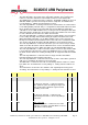
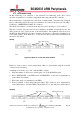
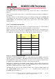
Writing
Figure 3-1 Write to a slave with 10 bit address
Figure 3-1 shows a write to a slave with a 10-bit address, to perform this using the controller
one must do the following:
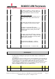
Assuming we are in the ‘stop’ state: (and the FIFO is empty)
1. Write the number of data bytes to written (plus one) to the I2CDLEN register.
2. Write ‘XXXXXXXX’ to the FIFO where ‘XXXXXXXX’ are the least 8 significant bits
of the 10-bit slave address.
3. Write other data to be transmitted to the FIFO.
4. Write ‘11110XX’ to Slave Address Register where ‘XX’ are the two most significant bits
of the 10-bit address. Set I2CC.READ = 0 and I2CC.ST = 1, this will start a write transfer.
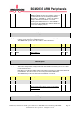
Reading
Stop
Start
Slave acknowledge
Repeat Start
Master acknowledge
Slave acknowledge