
Datasheet

06 February 2012 Broadcom Europe Ltd. 406 Science Park Milton Road Cambridge CB4 0WW Page 23
© 2012 Broadcom Corporation. All rights reserved
8
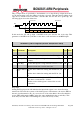
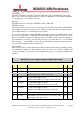
Out rising
If 1 data is clocked out on the rising edge of the SPI
clock
If 0 data is clocked out on the falling edge of the SPI
clock
R/W 0
7
Invert SPI
CLK
If 1 the 'idle' clock line state is high.
If 0 the 'idle' clock line state is low.
R/W 0
6
Shift out MS
bit first
If 1 the data is shifted out starting with the MS bit.
(bit 15 or bit 11)
If 0 the data is shifted out starting with the LS bit. (bit
0)
R/W 0
5:0 Shift length Specifies the number of bits to shift
This field is ignored when using 'variable shift' mode
R/W 0
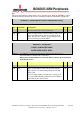
Invert SPI CLK
Changing this bit will immediately change the polarity of the SPI clock output. It is
recommended not to do this when also the CS is active as the connected devices will see this
as a clock change.
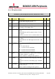
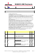
DOUT hold time
Because the interface runs of fast silicon the MOSI hold time against the clock will be very
short. This can cause considerable problems on SPI slaves. To make it easier for the slave to
see the data the hold time of the MOSI out against the SPI clock out is programmable.
No hold time
MOSI
CLK
With hold time
MOSI
CLK
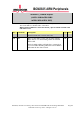
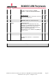
Variable width
In this mode the shift length is taken from the transmit FIFO. The transmit data bits 28:24 are
used as shift length and the data bits 23:0 are the actual transmit data. If the option 'shift MS
out first' is selected the first bit shifted out will be bit 23. The receive data will arrive as
normal.
Variable CS
This mode is used together with the variable width mode. In this mode the CS pattern is
taken from the transmit FIFO. The transmit data bits 31:29 are used as CS and the data bits
23:0 are the actual transmit data. This allows the CPU to write to different SPI devices
without having to change the CS bits. However the data length is limited to 24 bits.
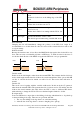
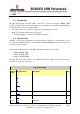
Post-input mode
Some rare SPI devices output data on the falling clock edge which then has to be picked up
on the next falling clock edge. There are two problems with this:
1. The very first falling clock edge there is no valid data arriving.
2. After the last clock edge there is one more 'dangling' bit to pick up.