
Datasheet

06 February 2012 Broadcom Europe Ltd. 406 Science Park Milton Road Cambridge CB4 0WW Page 204
© 2012 Broadcom Corporation. All rights reserved
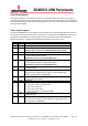
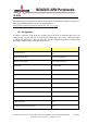
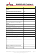
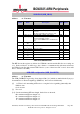
USB VBUS (USB_VBUS)
Address 0x 7E98 0088
Bit
Number
Field
Name
Description
Read/
Write
Reset
31-20 - Unused - 0
19-16 axi_priority Sets the USB AXI priority level R/W 0
15:10 - Unused - 0
9 vbus_irq 1=one or more bits of [6:4] have changed since
last read.
This bit is cleared when the register is read.
RC 0
8 vbus_irq_en 1=Enable IRQ on VBUS status change R/W 0
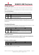
7 afe_non_driving 1=USB PHY AFE pull ups/pull downs are off
0=Normal USB AFE operation
(Has no effect if MDIO mode is enabled in the
phy)
R/W 0
6 utmisrp_dischrgv
bus
Drive VBUS R 0
5 utmisrp_chrgvbu
s
Charge VBUS R 0
4 utmiotg_drvvbus
Discharge VBUS R 0
3 utmiotg_avalid A session Valid R/W 0
2 utmiotg_bvalid B session Valid R/W 0
1 utmiotg_vbusvali
d
VBUS valid R/W 0
0 utmisrp_sessend
Session end R/W 0
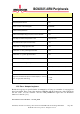
Table 15-3 USB MDIO data
The RW bits in this register are fed into the USB2.0 controller and the RO bits are coming out
of it. In the real device, it will be up to the software to communicate this information between
the USB2.0 controller and external VBUS device (some of these have I2C control, others will
have to interface via GPIO).
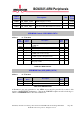
USB AHB configuration (USB_GAHBCFG)
Address 0x 7E98 0008
The USB_GAHBCFG register has been adapted. Bits [4:1] which are marked in the Synopsys
documentation as "Burst Length/Type (HBstLen)" have been used differently.
[4] 1 = Wait for all outstanding AXI writes to complete before signalling (internally) that
DMA is done.
0 = don't wait.
[3] Not used
[2:1] Sets the maximum AXI burst length, but the bits are inverted,
00 = maximum AXI burst length of 4,
01 = maximum AXI burst length of 3,
10 = maximum AXI burst length of 2
11 = maximum AXI burst length of 1