
Datasheet

06 February 2012 Broadcom Europe Ltd. 406 Science Park Milton Road Cambridge CB4 0WW Page 196
© 2012 Broadcom Corporation. All rights reserved
14 Timer (ARM side)
14.1 Introduction
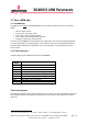
The ARM Timer is based on a ARM AP804, but it has a number of differences with the standard
SP804:
• There is only one timer.
• It only runs in continuous mode.
• It has a extra clock pre-divider register.
• It has a extra stop-in-debug-mode control bit.
• It also has a 32-bit free running counter.
The clock from the ARM timer is derived from the system clock. This clock can change dynamically
e.g. if the system goes into reduced power or in low power mode. Thus the clock speed adapts to
the overal system performance capabilities. For accurate timing it is recommended to use the
system timers.
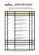
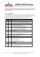
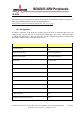
14.2 Timer Registers:
The base address for the ARM timer register is 0x7E00B000.
Address
offset
8
Description
0x400
Load
0x404
Value
(Read Only)
0x408
Control
0x40C
IRQ Clear/Ack
(Write only)
0x410
RAW IRQ
(Read Only)
0x414
Masked IRQ
(Read Only)
0x418
Reload
0x41C
Pre
-
divider
(Not in real 804!)
0x420
Free running counter (Not in real 804!)
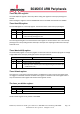
Timer Load register
The timer load register sets the time for the timer to count down. This value is loaded into the timer
value register after the load register has been written or if the timer-value register has counted
down to 0.
8
This is the offset which needs to be added to the base address to get the full hardware address.