
Datasheet

06 February 2012 Broadcom Europe Ltd. 406 Science Park Milton Road Cambridge CB4 0WW Page 185
© 2012 Broadcom Corporation. All rights reserved
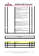
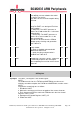
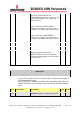
3 STP2 Two stop bits select. If this bit is set to 1,
two stop bits are transmitted at the end of
the frame. The receive
logic does not check for two stop bits being
received.
RW 0x0
2 EPS Even parity select. Controls the type of
parity the UART uses during transmission
and reception:
0 = odd parity. The UART generates or
checks for an odd number of 1s in the data
and parity bits.
1 = even parity. The UART generates or
checks for an even number of 1s in the
data and parity bits.
This bit has no effect when the PEN bit
disables parity checking and generation.
See Table 25 9.
RW 0x0
1 PEN Parity enable:
0 = parity is disabled and no parity bit
added to the data frame
1 = parity checking and generation is
enabled. See Table 25 9.
RW 0x0
0 BRK Send break. If this bit is set to 1, a low-level
is continually output on the TXD output,
after completing transmission of the current
character.
RW 0x0
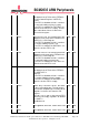
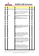
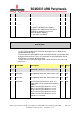
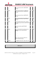
CR Register
Synopsis
The UART_CR Register is the control register.
NOTE:
To enable transmission, the TXE bit and UARTEN bit must be set to 1.
Similarly, to enable reception, the RXE bit and UARTEN bit, must be set to 1.
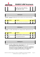
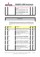
NOTE:
Program the control registers as follows:
1. Disable the UART.
2. Wait for the end of transmission or reception of the current character.
3. Flush the transmit FIFO by setting the FEN bit to 0 in the Line Control
Register, UART_LCRH.
4. Reprogram the Control Register, UART_CR.
5. Enable the UART.