
Datasheet

06 February 2012 Broadcom Europe Ltd. 406 Science Park Milton Road Cambridge CB4 0WW Page 176
© 2012 Broadcom Corporation. All rights reserved
• The deltas of the modem status signals are not available.
The following 16C650 UART features are not supported:
• 1.5 stop bits (1 or 2 stop bits only are supported)
• Independent receive clock.
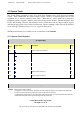
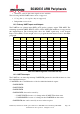
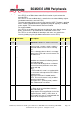
13.2 Primary UART Inputs and Outputs
The UART has two primary inputs RXD, nCTS and two primary outputs TXD, nRTS. The
remaining signals like SRIN, SROUT, OUT1, OUT2, DSR, DTR, and RI are not supported in
this implementation. The following table shows the UART signals map on the General
Purpose I/O (GPIO). For the insight on how to program alternate function refer to the GPIO
paragraph.
Pull
ALT0
ALT1
ALT2
ALT3
ALT4
ALT5
GPIO14 Low TXD0
GPIO15 Low RXD0
GPIO16 Low CTS0
GPIO17 Low RTS0
GPIO30 Low CTS0
GPIO31 Low RTS0
GPIO32 Low TXD0
GPIO33 Low RXD0
GPIO36 High TXD0
GPIO37 Low RXD0
GPIO38 Low RTS0
GPIO39 Low CTS0
Table 13-1 UART Assignment on the GPIO Pin map
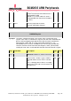
13.3 UART Interrupts
The UART has one intra-chip interrupt UARTINTR generated as the OR-ed function of the
five individual interrupts.
• UARTINTR, this is an OR function of the five individual masked outputs:
• UARTRXINTR
• UARTTXINTR
• UARTRTINTR
• UARTMSINTR, that can be caused by:
— UARTCTSINTR, because of a change in the nUARTCTS modem status
— UARTDSRINTR, because of a change in the nUARTDSR modem status.
• UARTEINTR, that can be caused by an error in the reception: