
Datasheet

REFERENCE: C6357-M-1398 BROADCOM PROPRIETARY AND CONFIDENTIAL PAGE 172
© 2012 Broadcom Corporation.
All rights reserved
Broadcom Europe Ltd. 406 Science Park Milton Road Cambridge CB4 0WW
12 System Timer
The System Timer peripheral provides four 32-bit timer channels and a single 64-bit free running
counter. Each channel has an output compare register, which is compared against the 32 least
significant bits of the free running counter values. When the two values match, the system timer
peripheral generates a signal to indicate a match for the appropriate channel. The match signal is then
fed into the interrupt controller. The interrupt service routine then reads the output compare register
and adds the appropriate offset for the next timer tick. The free running counter is driven by the timer
clock and stopped whenever the processor is stopped in debug mode.
The Physical (hardware) base address for the system timers is 0x7E003000.
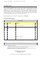
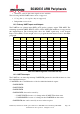
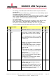
12.1 System Timer Registers
ST Address Map
Address
Offset
Register Name Description Size
0x0
CS
System Timer Control/Status
32
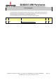
0x4
CLO
System Timer Counter Lower 32 bits
32
0x8
CHI
System Timer Counter Higher 32 bits
32
0xc
C0
System Timer Compare 0
32
0x10
C1
System
Timer Compare 1
32
0x14
C2
System Timer Compare 2
32
0x18
C3
System Timer Compare 3
32
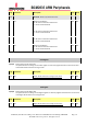
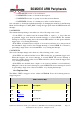
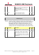
CS Register
Synopsis
System Timer Control / Status.
This register is used to record and clear timer channel comparator matches. The system timer match bits
are routed to the interrupt controller where they can generate an interrupt.
The M0-3 fields contain the free-running counter match status. Write a one to the relevant bit to clear the
match detect status bit and the corresponding interrupt request line.