
Datasheet

06 February 2012 Broadcom Europe Ltd. 406 Science Park Milton Road Cambridge CB4 0WW Page 147
© 2012 Broadcom Corporation. All rights reserved
Synopsis
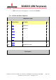
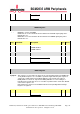
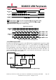
This register is used to define the range for the corresponding channel. In PWM mode
evenly distributed pulses are sent within a period of length defined by this register. In
serial mode serialised data is transmitted within the same period. If the value in
PWM_RNGi is less than 32, only the first PWM_RNGi bits are sent resulting in a
truncation. If it is larger than 32 excess zero bits are padded at the end of data. Default
value for this register is 32.
Note: Channels 3 and 4 are not available in B0 and corresponding Channel Range
Registers are ignored.
Bit(s)
Field Name
Description
Type
Reset
31:0 PWM_RNGi Channel i Range RW 0x20
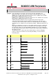
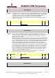
DAT2 Register
Synopsis
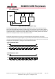
This register stores the 32 bit data to be sent by the PWM Controller when USEFi is 1.
In PWM mode data is sent by pulse width modulation: the value of this register defines
the number of pulses which is sent within the period defined by PWM_RNGi. In
serialiser mode data stored in this register is serialised and transmitted.
Note: Channels 3 and 4 are not available in B0 and corresponding Channel Data
Registers are ignored.
Bit(s)
Field Name
Description
Type
Reset
31:0 PWM_DATi Channel i Data RW 0x0