
Datasheet

06 February 2012 Broadcom Europe Ltd. 406 Science Park Milton Road Cambridge CB4 0WW Page 140
© 2012 Broadcom Corporation. All rights reserved
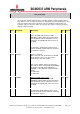
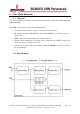
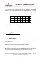
When MSEN=1, PWM block does not use the algorithm explained above, instead it sends serial data
with the M/S ratio as in the picture below. M is the data to be sent, and S is the range. This mode
may be preferred if high frequency modulation is not required or has negative effects. Channel
sends its output continuously as long as data register is used, or buffer is used and it is not empty.
Serial bit transmission when M/S Mode enabled
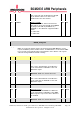
Serialiser mode: Each channel is also capable of working as a serialiser. In this mode data written in
buffer or the data register is sent serially.
9.5 Quick Reference
• PWM DMA is mapped to DMA channel 5.
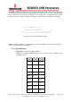
• GPIOs are assigned to PWM channels as below. Please refer to GPIO section
for further details:
PWM0
PWM1
GPIO 12
Alt Fun 0
-
GPIO 13
-
Alt Fun 0
GPIO 18
Alt Fun 5
-
GPIO 19
-
Alt Fun 5
GPIO 40
Alt Fun 0
-
GPIO 41
-
Alt Fun 0
GPIO 45
-
Alt Fun 0
GPIO 52
Alt Fun 1
-
GPIO 53
-
Alt Fun 1