
Datasheet

06 February 2012 Broadcom Europe Ltd. 406 Science Park Milton Road Cambridge CB4 0WW Page 139
© 2012 Broadcom Corporation. All rights reserved
9.3 PWM Implementation
A value represented as a ratio of N/M can be transmitted along a serial channel with pulse width
modulation in which the value is represented by the duty cycle of the output signal. To send value
N/M within a periodic sequence of M cycles, output should be 1 for N cycles and 0 for (M-N) cycles.
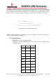
The desired sequence should have 1’s and 0’s spread out as even as possible so that during any
arbitrary period of time duty cycle achieves closest approximation of the value. This can be shown in
the following table where 4/8 is modulated (N= 4, M= 8).
Bad
0
0
0
0
1
1
1
1
0
0
0
0
Fair
0
0
1
1
0
0
1
1
0
0
1
1
Good
0
1
0
1
0
1
0
1
0
1
0
1
Sequence which gives the ‘good’ approximation from the table above can be achieved by the
following algorithm:
where context is a register which stores the result of the addition/subtractions.
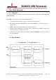
9.4 Modes of Operation
PWM controller consists of two independent channels (pwm_chn in block diagram) which
implement the pwm algorithm explained in section 1.3. Each channel can operate in either pwm
mode or serialiser mode.
PWM mode: There are two sub-modes in PWM mode: MSEN=0 and MSEN=1.
When MSEN=0, which is the default mode, data to be sent is interpreted as the value N of the
algorithm explained above. Number of clock cycles (range) used to send data is the value M of the
algorithm. Pulses are sent within this range so that the resulting duty cycle is N/M. Channel sends its
output continuously as long as data register is used, or buffer is used and it is not empty.
1.
Set context = 0
2. context = context + N
3. if (context >= M)
context = context – M
send 1
else