
Datasheet

06 February 2012 Broadcom Europe Ltd. 406 Science Park Milton Road Cambridge CB4 0WW Page 136
© 2012 Broadcom Corporation. All rights reserved
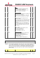
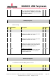
3 RXERR RX Error Interrupt Status / Clear
This bit indicates an interrupt occurred on RX
FIFO Error.
Writing 1 to this bit clears it. Writing 0 has no
effect.
RW 0x0
2 TXERR TX Error Interrupt Status / Clear
This bit indicates an interrupt occurred on TX
FIFO Error.
Writing 1 to this bit clears it. Writing 0 has no
effect.
RW 0x0
1 RXR RX Read Interrupt Status / Clear
This bit indicates an interrupt occurred on RX
Read.
Writing 1 to this bit clears it. Writing 0 has no
effect.
RW 0x0
0 TXW TX Write Interrupt Status / Clear
This bit indicates an interrupt occurred on TX
Write.
Writing 1 to this bit clears it. Writing 0 has no
effect.
RW 0x0
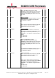
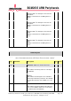
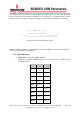
GRAY Register
Synopsis
This register is used to control the gray mode generation. This is used to put the PCM
into a special data/strobe mode. This mode is under 'best effort ' contract.
Bit(s)
Field Name
Description
Type
Reset
31:22
Reserved
-
Write as 0, read as don't care
21:16 RXFIFOLEVEL The Current level of the RXFIFO
This indicates how many words are currently in
the RXFIFO.
RO 0x0
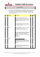
15:10 FLUSHED The Number of bits that were flushed into the
RXFIFO
This indicates how many bits were valid when
the flush operation was performed. The valid bits
are from bit 0 upwards. Non-valid bits are set to
zero.
RO 0x0
9:4 RXLEVEL The Current fill level of the RX Buffer
This indicates how many GRAY coded bits have
been received. When 32 bits are received, they
are written out into the RXFIFO.
RO 0x0