
Datasheet

06 February 2012 Broadcom Europe Ltd. 406 Science Park Milton Road Cambridge CB4 0WW Page 133
© 2012 Broadcom Corporation. All rights reserved
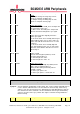
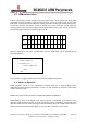
TXC_A Register
Synopsis
Sets the Channel configurations for Transmitting. This sets the position and width of
the 2 transmit channels within the frame. The two channels cannot overlap, however
they channel 1 can come after channel zero, although the first data will always be used
in the first channel in the frame. Channels can also straddle the frame begin end
boundary as that is set by the frame sync position. This register cannot be changed
whilst the PCM is running.
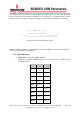
Bit(s)
Field Name
Description
Type
Reset
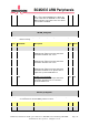
31 CH1WEX Channel 1 Width Extension Bit
This is the MSB of the channel 1 width
(CH1WID). It allows widths greater than 24 bits
to be programmed and is added here to keep
backwards compatibility with older versions of
the PCM
RW 0x0
30 CH1EN Channel 1 Enable
0 = Channel 1 disabled and no data is taken
from the TX FIFO and transmitted on channel 1.
1 = Channel 1 enabled.
RW 0x0
29:20 CH1POS Channel 1 Position
This sets the bit clock at which the first bit (MS
bit) of channel 1 data occurs in the frame.
0 indicates the first clock of frame.
RW 0x0
19:16 CH1WID Channel 1 Width
This sets the width of channel 1 in bit clocks.
This field has been extended with the CH1WEX
bit giving a total width of (CH1WEX* 16) +
CH1WID + 8. The Maximum supported width is
32 bits.
0 = 8 bits wide
1 = 9 bits wide
RW 0x0
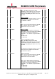
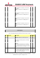
15 CH2WEX Channel 2 Width Extension Bit
This is the MSB of the channel 2 width
(CH2WID). It allows widths greater than 24 bits
to be programmed and is added here to keep
backwards compatibility with older versions of
the PCM
RW 0x0
14 CH2EN Channel 2 Enable
0 = Channel 2 disabled and no data is taken
from the TX FIFO and transmitted on channel 2.
1 = Channel 2 enabled.
RW 0x0