
Datasheet

06 February 2012 Broadcom Europe Ltd. 406 Science Park Milton Road Cambridge CB4 0WW Page 131
© 2012 Broadcom Corporation. All rights reserved
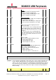
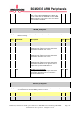
22 CLKI Clock Invert this logically inverts the PCM_CLK
signal.
0 = Outputs change on rising edge of clock,
inputs are sampled on falling edge.
1 = Outputs change on falling edge of clock,
inputs are sampled on rising edge.
RW 0x0
21 FSM Frame Sync Mode
0 = Master mode. The PCM_FS is an output and
we generate the frame sync.
1 = Slave mode. The PCM_FS is an input and
we lock onto the incoming frame sync signal.
RW 0x0
20 FSI Frame Sync Invert This logically inverts the
frame sync signal.
0 = In master mode, FS is normally low and goes
high to indicate frame sync. In slave mode, the
frame starts with the clock where FS is a 1 after
being a 0.
1 = In master mode, FS is normally high and
goes low to indicate frame sync. In slave mode,
the frame starts with the clock where FS is a 0
after being a 1.
RW 0x0
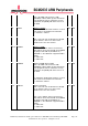
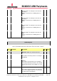
19:10 FLEN Frame Length
Sets the frame length to (FLEN+1) clocks.
Used only when FSM == 0.
1 = frame length of 2 clocks.
2 = frame length of 3 clocks. etc
RW 0x0
9:0 FSLEN Frame Sync Length
Sets the frame sync length to (FSLEN) clocks.
This is only used when FSM == 0.
PCM_FS will remain permanently active if
FSLEN >= FLEN.
0 = frame sync pulse is off.
1 = frame sync pulse is 1 clock wide. etc
RW 0x0
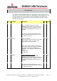
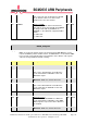
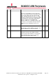
RXC_A Register
Synopsis
Sets the Channel configurations for Receiving. This sets the position and width of the 2
receive channels within the frame. The two channels cannot overlap, however they
channel 1 can come after channel zero, although the first data will always be from the
first channel in the frame. Channels can also straddle the frame begin end boundary
as that is set by the frame sync position. This register cannot be changed whilst the
PCM is running.
Bit(s)
Field Name
Description
Type
Reset