
Datasheet

06 February 2012 Broadcom Europe Ltd. 406 Science Park Milton Road Cambridge CB4 0WW Page 130
© 2012 Broadcom Corporation. All rights reserved
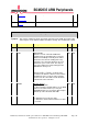
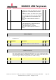
28 CLK_DIS PCM Clock Disable
1 = Disable the PCM Clock.
This cleanly disables the PCM clock. This
enables glitch free clock switching between an
internal and an uncontrollable external clock.
The PCM clock can be disabled, and then the
clock source switched, and then the clock re-
enabled.
0 = Enable the PCM clock.
RW 0x0
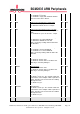
27 PDMN PDM Decimation Factor (N)
0 = Decimation factor 16.
1 = Decimation factor 32.
Sets the decimation factor of the CIC decimation
filter.
RW 0x0
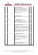
26 PDME PDM Input Mode Enable
0 = Disable PDM (classic PCM input).
1 = Enable PDM input filter.
Enable CIC filter on input pin for PDM inputs. In
order to receive data RXON must also be set.
RW 0x0
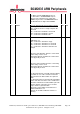
25 FRXP Receive Frame Packed Mode
0 = The data from each channel is written into
the RX FIFO.
1 = The data from both RX channels is merged
(1st channel is in the LS half) and then written to
the RX FIFO as a single 2x16 bit packed mode
word.
First received channel in the frame goes into the
LS half word. If the received data is larger than
16 bits, the upper bits are truncated. The
maximum channel size is 16 bits.
RW 0x0
24 FTXP Transmit Frame Packed Mode
0 = Each TX FIFO word is written into a single
channel.
1 = Each TX FIFO word is split into 2 16 bit
words and used to fill both data channels in the
same frame. The maximum channel size is 16
bits.
The LS half of the word is used in the first
channel of the frame.
RW 0x0
23 CLKM PCM Clock Mode
0 = Master mode. The PCM CLK is an output
and drives at the MCLK rate.
1 = Slave mode. The PCM CLK is an input.
RW 0x0