
Datasheet

06 February 2012 Broadcom Europe Ltd. 406 Science Park Milton Road Cambridge CB4 0WW Page 124
© 2012 Broadcom Corporation. All rights reserved
If a FIFO error occurs during operation in which 2 data channels are being used then the
synchronisation of the data may be lost. This can be recovered by either of these two methods:
a) Disable transmit and receive (TXON and RXON =0). Clear the FIFO’s (RXCLR and
TXCLR =1). Note that it may take up to 2 PCM clocks for the FIFOs to be physically
cleared after initiating a clear. Then preload the transmit FIFO and restart
transmission. This of course loses the data in the FIFO and further interrupts the data
flow to the external device.
b) Examine the TXSYNC and RXSYNC flags. These flags indicate if the amount of data in the FIFO
is a whole number of frames, automatically taking into account where we are in the current
frame being transmitted or received. Thus, providing an even number of samples was read
or written to the FIFOs, then if the flags are set then this indicates that a single word needs
to be written or read to adjust the data. Normal exchange of data can then proceed (where
the first word in a data pair is for channel 1). This method should cause less disruption to the
data stream.
8.6 PDM Input Mode Operation
The PDM input mode is capable of interfacing with two digital half-cycle PDM microphones
and implements a 4
th
order CIC decimation filter with a selectable decimation factor. The
clock input of the microphones is shared with the PCM output codec and it should be
configured to provide the correct clock rate for the microphones. As a result it may be
necessary to add a number of padding bits into the PCM output and configure the output
codec to allow for this.
When using the PDM input mode the bit width and the rate of the data received will depend
on the decimation factor used. Once the data has been read from the peripheral a further
decimation and filtering stage will be required and can be implemented in software. The
software filter should also correct the droop introduced by the CIC filter stage. Similarly a
DC correction stage should also be employed.
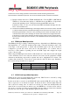
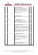
PDMN PCM_CLK (MHz)
Peripheral Output Format
OSR Fs
0 (N=16) 3.072
16 bits unsigned
4 48kHz
1 (N=32) 3.072 20 bits unsigned 2 48kHz
Table 8-1 PDM Input Mode Configuration
8.7 GRAY Code Input Mode Operation
GRAY mode is used for an incoming data stream only. GRAY mode is selected by setting
the enable bit (EN) in the PCM_GRAY register.
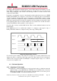
In this mode data is received on the PCM_DIN (data) and the PCM_FS (strobe) pins. The
data is expected to be in data/strobe format. In this mode data is detected when either the
data or the strobe change state. As each bit is received it is written into the RX buffer and
when 32 bits are received they are written out to the RXFIFO as a 32 bit word. In order for
this mode to work the user must program a PCM clock rate which is 4 times faster then the
gray data rate. Also the gray coded data input signals should be clean.