
Datasheet

06 February 2012 Broadcom Europe Ltd. 406 Science Park Milton Road Cambridge CB4 0WW Page 100
© 2012 Broadcom Corporation. All rights reserved
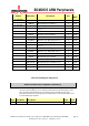
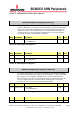
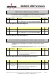
Table 6-25 – GPIO Asynchronous rising Edge Detect Status Register 1
GPIO Asynchronous Falling Edge Detect Enable Registers (GPAFENn)
S
YNOPSIS
The asynchronous falling edge detect enable registers define the pins for which a
asynchronous falling edge transition sets a bit in the event detect status registers
(GPEDSn). Asynchronous means the incoming signal is not sampled by the system
clock. As such falling edges of very short duration can be detected.
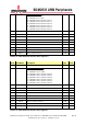
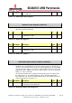
Bit(s) Field Name Description Type Reset
31-0 AFENn (n=0..31)
0 = Asynchronous falling edge detect disabled on GPIO
pin n.
1 = Asynchronous falling edge on GPIO pin n sets
corresponding bit in EDSn.
R/W 0
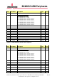
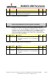
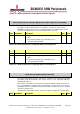
Table 6-26 – GPIO Asynchronous Falling Edge Detect Status Register 0
Bit(s) Field Name Description Type Reset
31-22 -
Reserved
R 0
21-0 AFENn (n=32..53)
0 = Asynchronous falling edge detect disabled on GPIO
pin n.
1 = Asynchronous falling edge on GPIO pin n sets
corresponding bit in EDSn.
R/W 0
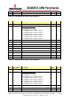
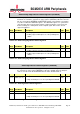
Table 6-27 – GPIO Asynchronous Falling Edge Detect Status Register 1
GPIO Pull-up/down Register (GPPUD)
S
YNOPSIS
The GPIO Pull-up/down Register controls the actuation of the internal pull-up/down
control line to ALL the GPIO pins. This register must be used in conjunction with the 2
GPPUDCLKn registers.
Note that it is not possible to read back the current Pull-up/down settings and so it is the
users’ responsibility to ‘remember’ which pull-up/downs are active. The reason for this is
that GPIO pull-ups are maintained even in power-down mode when the core is off, when
all register contents is lost.
The Alternate function table also has the pull state which is applied after a power down.
Bit(s) Field Name Description Type Reset