
User Manual

10
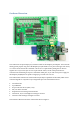
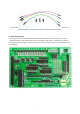
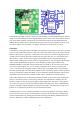
Figure 7: Power jumper installed in header J7: photo on left, diagram on right
The diagram on the right of Figure 7 above is our first example of a wiring diagram based on the blue
and grey circuit board diagram. These diagrams indicate pins via black circles around the locations of
pins on the board, and show connections as black lines between the circles. The diagram does not
indicate directly whether the two pins should be joined by straps (wires) or jumpers. Generally, if the
two pins are right next to each other, use a jumper, and if they are further apart, use a strap.
GPIO Pins
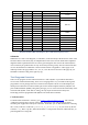
The header J2, to the right of the text „Raspberry Pi Gertboard‟ on the board, provides access to all the
I/O pins on the GPIO header. There are 26 pins in J1 (the socket which connects the Gertboard to the
Raspberry Pi) but only 17 pins in J2: 3 of the pins in J1 are power (3.3V and 5V) and ground, and 6
are DNC (do not connect). The labels on these pins, GP0, GP1, GP4, GP7, etc, may initially seem a
little arbitrary, as there are some obvious gaps, and the numbers do not correspond with the pin
numbers on the GPIO header J1. These labels are important however: they correspond with the signal
names used by the BCM2835, the processor on the Raspberry Pi (RPi). Signal GPIOn on the
BCM2835 datasheet corresponds to the pin labelled GPn on header J2. At least, this was true of the
first version of the Raspberry Pi (“rev1”). Starting in September 2012, revision 2 Raspberry Pis
(“rev2”) were starting to be shipped. On the rev2 RPis, some of the GPIO pins have been changed.
The GPIO port that used to be controlled by GPIO21 is now controlled by GPIO27, and the ports that
used to be controlled by GPIO0 and GPIO1 are now controlled by GPIO2 and GPIO3. The rest have
remained the same. The first three columns of Table 1 below summarize the current situation.
Some of the GPIO pins have an alternate function that are made use of in some of the test programs.
These are also shown in Table 1, in the last two columns. The ports that have nothing in the “Alt
function” column are only used as general purpose input/output in the code. In the C test programs,
we use macros to gain access to the alternative functions of the GPIO ports. This is explained in the
section on analogue to digital and digital to analogue converts (D/A and A/D tests in C, page 35). In
Python, we use packages to provide access to the alternative functions.
We mention the I
2
C bus use of GPIO0 and GPIO1 (or GPIO2 and GPIO3 for rev2 RPis) in Table 1
not because the I
2
C bus is used in the test programs, but because each of them has a 1800Ω pull-up
resistor on the Raspberry Pi, and this prevents them from being used with the pushbuttons (see the
section on Buffered I/O, LEDs, and Pushbuttons for more information).