
User Manual

9
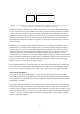
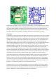
Figure 6: Two examples of ICs – an 8-pin and a 20-pin dual-inline package (DIP). In this package style, pin 1 is always
identified as the first pin anticlockwise from the package notch marking.
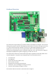
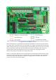
Integrated circuits (also known as ICs or chips), are marked Un. For example the I/O buffer chips are
U3, U4, and U5 (these are near the middle of the board), while the Atmel microcontroller is U8 (this
is below and to the left of U3 to U5). It is important to understand IC pin numbering. If the chip is
orientated so that the end with the semi-circle notch is to the left, then pin 1 is the leftmost pin in the
bottom row. Pin numbers increase in an anti-clockwise direction from there, as shown in Figure 6.
Knowing this means that the schematics in Appendix A can always be related to the pins on the ICs
on the Gertboard.
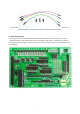
Headers (the rows of pins sticking up from the board) will be a frequently used component on the
Gertboard. They are labelled Jn. For example, there is a collection of headers along the left edge of
the board. They allow you to access the three chips on the left side of the board: J28 on top for the
analogue to digital chip, J29 below that for the digital to analogue chip, and J25 below that for the
Atmel microcontroller. It is a bit difficult to see the boundary between these headers on a fully
assembled board; it‟s much clearer on the blue and grey diagram in Figure 5. On the Gertboard circuit
board, each header with more than two pins has pin 1 marked with a square around it and a dot next to
it. The dot is most useful on the assembled board, but these dots don‟t appear in the blue and grey
diagram, so you can use the squares to find pin 1 there.
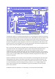
Not everything labelled Jn is a collection of pins. J1, at the bottom of the board, is the location of the
socket that connects the Gertboard to the Raspberry Pi. J19, at the top of the board (right of centre) is
a block of screw terminals that allow you to easily connect wires from a power supply and a motor.
Power on the Gertboard
Power pins are marked with their voltage, e.g. 5V or 3V3 (this means 3.3V). A 5V power supply
comes onto the board from the Raspberry Pi, and if you need this voltage it can be accessed from the
lower pin (marked 5V) on header J24 on the lower right-hand corner of the board. Ground is marked
with GND or a symbol.
The supply voltage (the voltage that acts as high or logical 1 on the board) is 3.3V. This is generated
from the 5V power pin in the J1 header by the components in the lower right corner of the board. To
send the 3.3V power supply to the components on the Gertboard, you need to install a jumper over the
top two pins of the header J7. It is near the lower right corner of the board; see the photo and diagram
in Figure 7. The open collector and motor controllers can handle higher voltages and have points to
attach external power supplies.
1 2
3
4
56
7
8
1 2 4
3 5 86
7
20 19 18
9 10
1112
13
14
1516
17