
User Manual

8
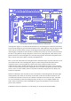
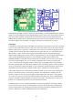
Figure 5: Diagram representing a bare Gertboard circuit board. The blue elements correspond to the white lines and
text, and the gray elements correspond to the silver coloured pads.
The diagram in Figure 5 is created from the files that were used to design the Gertboard circuit board.
The blue in the diagram is generated from the silkscreen file, which indicates where the white text and
lines on the circuit board will be. The grey in the diagram is generated from the solder mask file,
which roughly corresponds to where the silver conductive areas on the top of the circuit board will be.
We will be using this blue and grey diagram as a basis for our wiring diagrams, which show you the
pins that need to be connected together for each of the test programs. We use these diagrams because
they are much clearer than a photo of the fully assembled board.
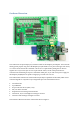
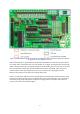
Have a close look at the white text on the photo of the Gertboard in Figure 4 (or the white text on your
own board or the blue text in the diagram in Figure 5). These labels provide information that is
required in order to connect together the various blocks of the Gertboard. Almost all of the
components have labels, and more importantly, the pins in the headers have labels. It isn‟t necessary
to be too concerned about many of the components, such as resistors and capacitors (labelled with Rn
and Cn, where n is some number). However the labels for headers, integrated circuits, diodes, and
switches are important.
Diodes are labelled Dn. The ones that you will be interested in are D1 through D12, the LEDs (light
emitting diodes). The LEDs are near the top of the board, on the left. The labels for them are a bit
crowded. Each LED has a resistor next to it and thus each label Dn has an Rm next to it. The LEDs
are easy to find when you have the board powered up, as they are a row of bright red lights. See
below, in the section Power on the GertboardPower (page 9) for information on how to provide
power to the Gertboard.
Pushbutton switches are labelled S1, S2, and S3 (they are located just beneath the LEDs).